
Method and an apparatus for twisting and tightening a wire

a technology of twisting and tightening wires, applied in the direction of wrapping/bundling articles, packaging, constructions, etc., can solve the problems of difficult to achieve satisfactory binding force, excessive use of binding wires, and high cost of binding reinforcement bars in concrete constructions

Inactive Publication Date: 2003-08-07
JENSEN KIM MICHAEL
View PDF3 Cites 58 Cited by
  • Summary
  • Abstract
  • Description
  • Claims
  • Application Information

AI Technical Summary

Benefits of technology

[0008] It is an object of the present invention to provide an improved method and apparatus for binding objects with a reduced amount of wire and an increased binding force.

Problems solved by technology

Binding reinforcement bars in concrete constructions is known to be a costly operation.
The result of the circular shaped jaws is typically an excessive overuse of binding wire.
Thereby the tightening force of the wire loop increases as the loop is being twisted and thereby a satisfactory binding force is difficult to achieve.

Method used


Image

  • Method and an apparatus for twisting and tightening a wire
  • Method and an apparatus for twisting and tightening a wire
  • Method and an apparatus for twisting and tightening a wire

Examples


Embodiment Construction

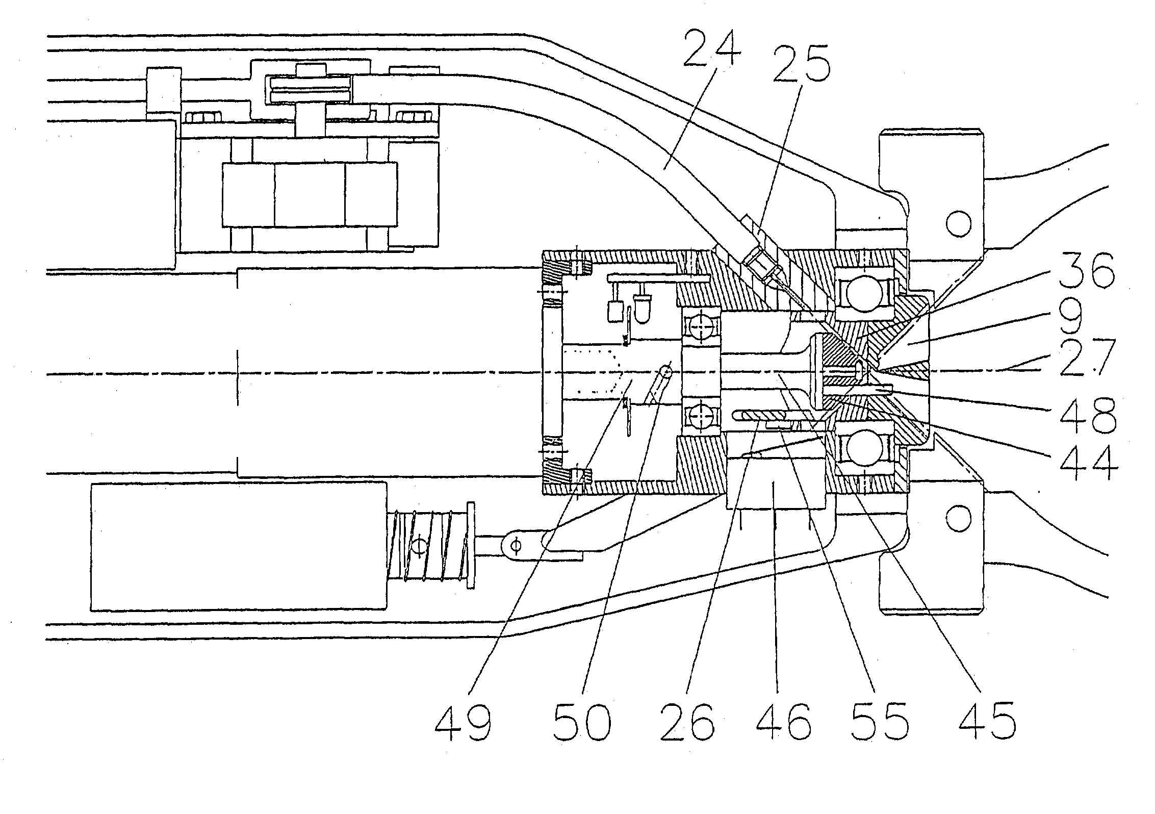
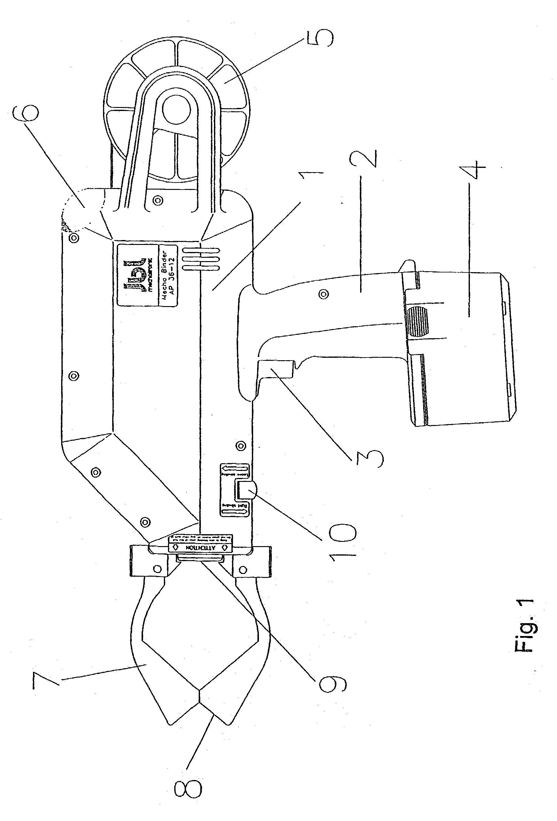
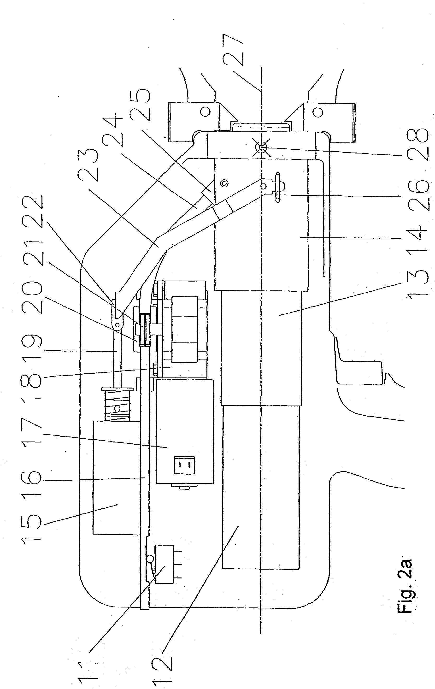
[0071] A preferred embodiment of the invention will now be described in details with reference to the drawing in which:

[0072] FIG. 1 shows a binder according to the present invention, seen from the side,

[0073] FIG. 2a shows the binder of FIG. 1 with the outer casing removed,

[0074] FIG. 2b shows details of a binder according to an alternative embodiment,

[0075] FIG. 3 shows details of the binder of FIGS. 1 and 2,

[0076] FIG. 4 shows the binder seen from above,

[0077] FIG. 5 shows an alternative embodiment of the binding arrangement,

[0078] FIG. 6 shows a preferred embodiment a polar head,

[0079] FIG. 7 shows a binding head,

[0080] FIG. 8 shows a spindle,

[0081] FIG. 9 shows a binder housing,

[0082] FIG. 10 shows a wire nozzle,

[0083] FIG. 11 shows an axial tightening device,

[0084] FIG. 12 shows a wire spindle lock,

[0085] FIG. 13 shows a wire lock,

[0086] FIG. 14 shows a sliding platform,

[0087] FIG. 15 shows the jaw attachment base,

[0088] FIG. 16 shows a jaw,

[0089] FIG. 17 shows a wire aligning...


PUM

PropertyMeasurementUnit
distanceaaaaaaaaaa
mutual distanceaaaaaaaaaa
diameteraaaaaaaaaa

Abstract

A method and apparatus for twisting and tightening a wire with a free end portion around at least two objects, e.g. iron bars for reinforced concrete, for binding the objects together. The method and apparatus enables a tighter and stronger binding to be performed even by means of a portable device and with the use of less binding wire than required by conventional devices.

Description

[0001] The present invention relates to a method and an apparatus for binding objects such as iron bars for reinforced concrete or for binding branches on trees or for binding any items together e.g. for the purpose of packing or securing items. More specifically the invention relates to an improved method and an apparatus for twisting and tightening a wire, the method and apparatus enables a tighter and stronger binding to be performed even by means of a portable device and with the use of less binding wire.DESCRIPTION OF THE PRIOR ART[0002] Binding reinforcement bars in concrete constructions is known to be a costly operation. By manual processes a wire is curled around the iron bars and by means of a wire cutter, the free ends of the wire is twisted. Resent considerations not only related to the costs of binding the bars but also related to the working environment, has lead to the development of hand held, portable devices for binding.[0003] EP 0751270 shows a device for binding ...

Claims


Application Information

Patent Timeline
Patent Type & Authority Applications(United States)
IPC IPC(8): B65B13/28E04G21/12
CPCE04G21/122B65B13/285E04G21/123
Inventor JENSEN, KIM MJENSEN, PER B
Owner JENSEN KIM MICHAEL
Learn More