Recording surface relief microstructure

a surface relief and microstructure technology, applied in the field of surface relief microstructure, can solve the problems of large size of the resultant spot, relatively cumbersome process,

Inactive Publication Date: 2003-08-14
DE LA RUE INT LTD
View PDF0 Cites 2 Cited by
  • Summary
  • Abstract
  • Description
  • Claims
  • Application Information

AI Technical Summary

Problems solved by technology

This process is relatively cumbersome to achieve and recently digital diffraction, dot-matrix or digital holographic printers have become available for producing holographic master resists for the security industry.
The problem with this known technique is that in order to achieve spectral purity it is desirable to decrease the cross-sectional area of each beam but the consequence of this is that the size of the resultant spot expands.

Method used


Image

  • Recording surface relief microstructure
  • Recording surface relief microstructure
  • Recording surface relief microstructure

Examples


Embodiment Construction

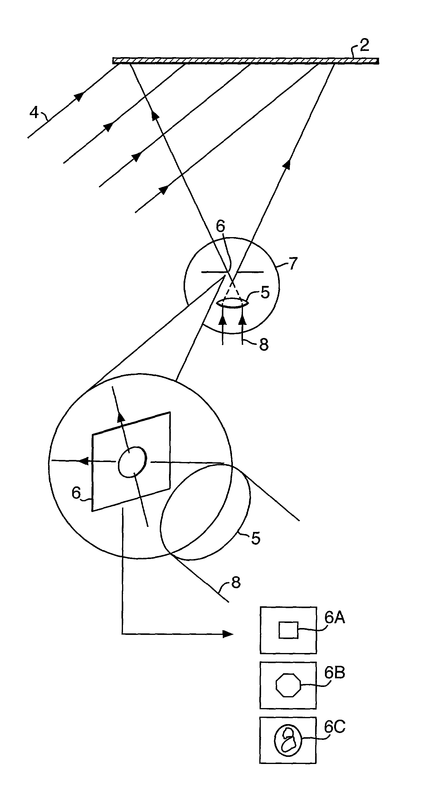
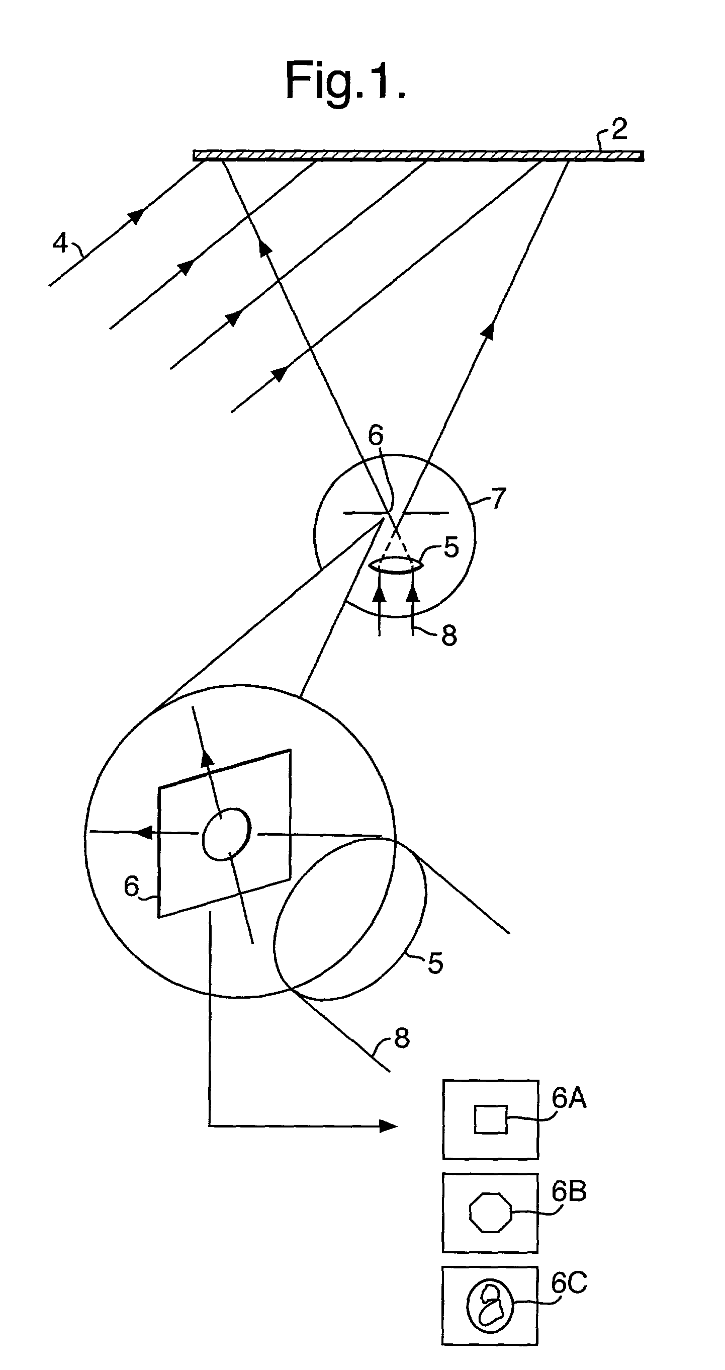
[0022] The preparation of a HOE for subsequent use in creating a dot-matrix hologram will be described with reference to FIG. 1.

[0023] Using the basic format for the recording of an H1 master hologram, a collimated reference beam 4 falls at a standard angle of reference upon a silver-halide recording plate 2. In place of artwork, lit by a diffuser screen from the rear, in a routine H1 production system, an objective lens 5 of some 60.times.magnification is used to illuminate fully the H1 (HOE) plate 2 with a beam 8. The beams 4,8 may originate from the same (or different) laser.

[0024] Using a spatial filter mounting system, a purpose-made pinhole 6 cut to a specific shape having a lateral dimension in the order of 12 microns is positioned in a micrometer-positioned x,y,z stage 7, fractionally in front of the focal point, such that the pinhole aperture is fully lit to achieve a "top-hat" distribution of light.

[0025] Development and bleaching of the recording plate 2 yields a HOE of h...


PUM


Abstract

A method of recording a surface relief microstructure in a record medium comprises: i) causing a coherent reconstruction or replay beam to impinge on a holographic optical element assembly, the holographic optical element assembly including a holographic optical element (HOE), the assembly causing selected portions of the beam to interfere at a focal region after diffraction by the holographic optical element so as to reconstruct a real image of an aperture previously used to construct the HOE; ii) locating a record medium at the focal region so that the real image is recorded; and, iii) causing relative movement between the record medium and the interfering beam portions and repeating steps i) and ii) so that the real image is recorded at a plurality of locations or pixels on the record medium.

Description

[0001] The invention relates to a method of recording a surface relief microstructure in a record medium.DESCRIPTION OF THE PRIOR ART[0002] Surface relief microstructures are used to create diffraction and holographic effects which find particular application in security features for use on documents of value such as identity cards, banknotes, and the like.[0003] Conventionally, such a microstructure is created in two stages. In a first stage, a H1 device is created by causing interference between a reference laser beam and an object beam which has impinged on an object. The H1 is then used subsequently upon exposure by a suitable conjugate beam to generate a real image which is recorded on a H2 record medium.[0004] This process is relatively cumbersome to achieve and recently digital diffraction, dot-matrix or digital holographic printers have become available for producing holographic master resists for the security industry. Dot-matrix holography is described in U.S. Pat. No. 6,0...

Claims


Application Information

Patent Timeline
Patent Type & Authority Applications(United States)
IPC IPC(8): G03H1/04
CPCG03H1/0404G03H2001/0439G03H2001/0473G03H2001/0482G03H2230/10G03H2210/55G03H2223/12G03H2225/31G03H2001/0497
Inventor HOLMES, BRIAN WILLIAMWILTSHIRE, JOHN DAVID
Owner DE LA RUE INT LTD
Why Eureka
Try Eureka