
Artificial nail tips

a nail tip and artificial technology, applied in the field of artificial nail tips, can solve the problems of tip cracking or weakening, discomfort for the wearer of the nail tip, and is normally not strong enough to withstand, so as to maintain the structural integrity

Inactive Publication Date: 2003-09-25
SWENSEN ALEXANDRA
View PDF6 Cites 26 Cited by
  • Summary
  • Abstract
  • Description
  • Claims
  • Application Information

AI Technical Summary

Benefits of technology

[0017] The current invention provides for flexibility while maintaining structural integrity against breaks, cracks and weakening.
[0018] It is the principal object of this invention to provide an improved and superior nail tip. It is a further object of the current invention to provide a nail tip having a "cutout" area on both sides which leaves a remaining area in the center of the attachment area, referred to as the "Wing".
[0019] It is also an object of the current invention to provide an artificial nail tip with a "cutout" area on both sides of a thinned attachment area ("Wing") the purpose of which is to provide for easier application and a more conforming and comfortably fitting nail tip to a variety of natural nail shapes. It is also an object of the current invention to provide a nail tip with a "Wing" attachment area where the remaining extension area of the tip is placed in such a position as to have the extension area of the nail tip be flush with the wearer's natural nail, creating an aesthetically more pleasing fingernail.

Problems solved by technology

The tip alone is normally not strong enough to withstand the stress that it is subject to by being on the end of a finger.
As one's hands are constantly in motion or being utilized for some purpose, the artificial nail tips are constantly getting knocked and hit, which can cause them to break.
However, this raises concerns on how securely the tip can be glued onto the natural nail.
However, every person's nails are slightly different, meaning not everyone will have a curve in their natural nail that is the same as the curve of the artificial nail tip that is being applied.
Frequently, during this stage of application, the stress caused by attempting to conform the artificial nail tip to the shape of the natural nail causes the tip to crack or weaken.
In addition, the mismatch in curvatures also provides discomfort to the wearer of the nail tip and provides difficulty in attaching and fitting the nail tips.
The wearer may experience discomfort when wearing such a nail tip due to the axial curvature of the nail tip squeezing or pinching the sides of the underlying natural nail.
The applier of the nail tip may experience difficulty in attaching and fitting the nail tip to the wearer because of the inability of the curvature of the nail tip to be deformed (e.g. flattened out) to properly fit the wearer's natural curvature without breaking, cracking or weakening.
There also exists the difficulty in filling the gap that is created between the nail tip and the underlying natural nail due to the curvature mismatch.
The wearer may also experience additional discomfort or even serious pain when wearing such a nail tip due to the glue or adhesive used to attach such a nail tip overflowing onto the wearers surrounding skin and underneath the natural nail.
The removal of such overflowed glue with the proper chemicals often times results in the integrity of the tip itself and its seal being compromised.
In addition, this force may make it difficult for an applier to determine the size of tip to be used on a wearer and to fit a nail tip to the wearer due to the difficulty in determining the extent the nail tip will deform to match the wearer's curvature.
Furthermore, it is difficult for an applier to determine the extent to which the nail tip may be deformed without breaking, cracking or weakening (i.e. while maintaining it's structural integrity).
It is typical for prior tips to break, crack, or become weakened when deformed to a certain extent.
However, snapping out the perforated area of the nail tip results in a rough or uneven fragments that must be filed or cut to ensure a smooth and aesthetically pleasing nail surface.
In addition, snapping out the perforated area may result in breaking or cracking the nail tip, or in weakening the structural stability of the nail tip.
However, the jagged pattern of the cutaway section advocated by this patent does not maintain the structural stability of the nail tip when the attachment area is deformed or flexed to conform to the shape of an underlying natural nail, especially to natural nails which are flat or inconsistently shaped.
However, the presence of a dual radius "V" design nail tip presents the same non-conforming to the curvature of the wearers natural nail as does all the other aforementioned nail tip designs.
The presence of the side walls of the dual radius design on the nail tips attachment area do not allow for comfort of fit or ease of blending the attachment area's "V" shape in to the wearers natural nail for an aesthetically pleasing surface.
In addition, the patent states that the molded thickness and design of the attachment area is such that it allows for ease of adaptability in conforming to the curvature of the wearers natural nail without undue structural integrity, however the pre-molded shape with it's thickness does not allow for the deforming to take place without excessive filling (e.g. blending and feathering) which can result in damage to the wearers natural nail and loss of structural integrity of the nail tip itself.
Furthermore, because of the presence of the side walls of the dual radius attachment area which when bonded to the natural nail, covers the natural nails end from the wearers side wall to side wall, the width of the finished product is such that it no longer is aesthetically pleasing.
Furthermore, the side walls can cause damage to the natural nail when the nail tip is removed, either intentionally or unintentionally by breaking or tearing of the nail tip.

Method used


Image

  • Artificial nail tips
  • Artificial nail tips
  • Artificial nail tips

Examples


Embodiment Construction

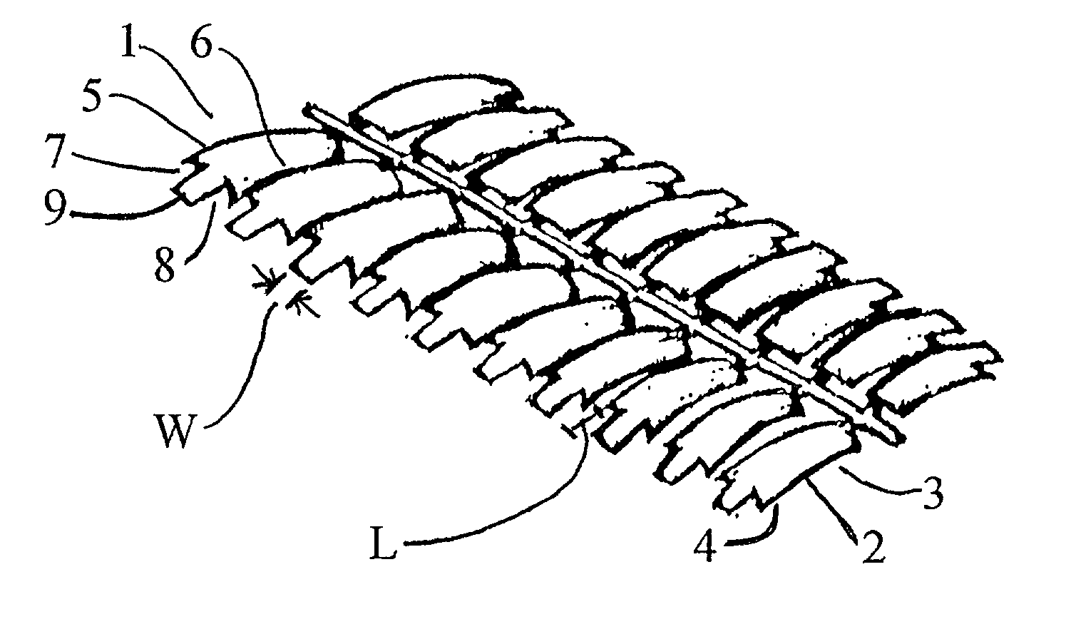
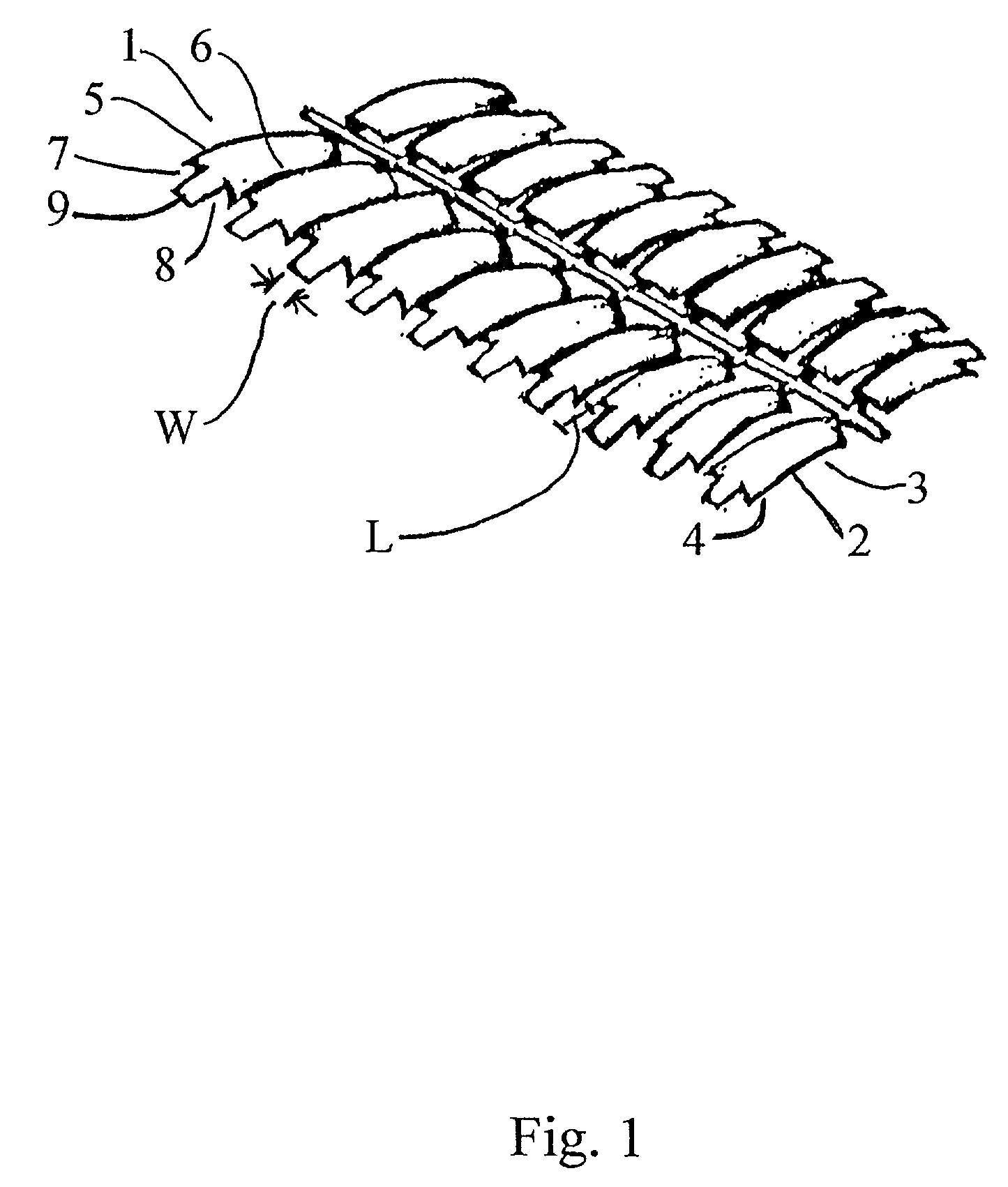
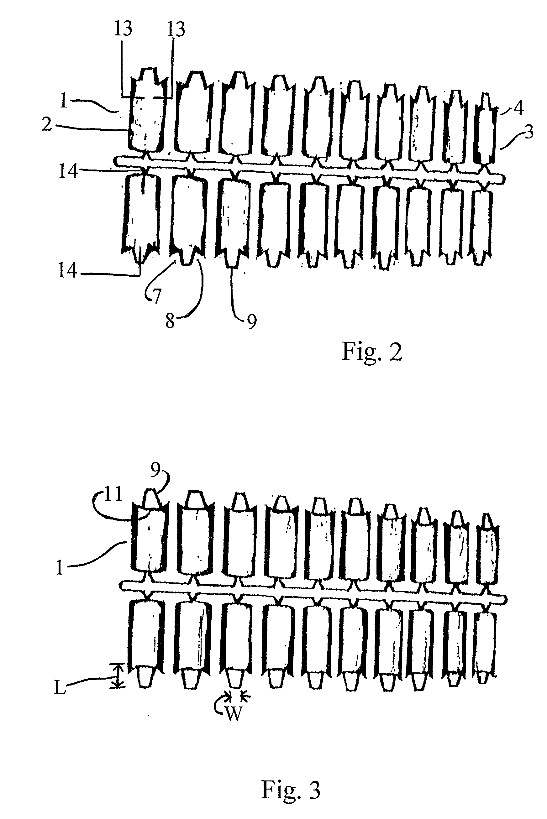
[0033] Referring first to FIG. 1, the current invention involves a nail tip 1 that has a body member 2, a front portion 3 of the body member 2, a back portion 4 of the body member 2, a first side 5 and a second side 6, a first cutout portion 7 on one side of said back portion 4 and a second cutout portion 8 on the opposing side of the back portion 4. The first cutout portion 7 and the second cutout portion 8 define a thinned attachment wing area 9 to provide a more flexible attachment area and, therefore, a more conforming fit of the nail tip 1 to a variety of natural nails. The first cutout portion 7 and second cutout portion 8 create the narrower attachment wing area 9 that has a more aesthetically pleasing look and results in a stronger finished nail product with less damage to the wearer's natural nail. In the preferred embodiment, the first cutout portion 7 and second cutout portion 8 of the nail tip 1 are achieved by pre-molding the nail tip 1 to include such portions; they ar...


PUM


Abstract

The present application relates to artificial nail tips, particularly artificial nail tips that have an attachment area with an axial curvature and two cutout portions which provide a comfortable and conforming fit to a variety of natural nails while maintaining structural integrity and minimizing damage to the natural nail. The axial curvature of the attachment area of the nail tips is of a single radius design. The cutout portions of the nail tips are on both sides of the attachment portion of the nail tips, leaving a center attachment area narrower and thinner than the remaining nail tip. The attachment area of the nail tip is in a shape that allows for conformation to all natural nails, regardless of the length or curvature of the natural nail while maintaining the strength of the natural nail and minimizing damage to the natural nail. The shape of the attachment area of the nail tip allows it to deform to the natural nail without losing structural integrity.

Description

[0001] 1. Field of Invention[0002] The present invention relates generally to artificial nail tips and more particularly to an artificial nail tip that has a shape that conforms to all natural nails, that minimizes damage to the natural nail and maintains structural integrity while providing for a more natural looking and stronger artificial nail extension.[0003] 2. Description of Prior Art[0004] Artificial nail tips have been used for many years to extend the natural nail, giving the wearer a longer looking fingernail. Normally, an artificial nail tip is made out of a plastic like material in the general shape of a rectangle. The back end, which serves as the attachment end, can vary in shape. However, the back end is usually rounded at the corners for comfort and fit to the natural nail bed. Furthermore, the attachment area of the artificial nail is also normally thinner as compared to the tip area to allow the artificial nail to blend into the natural nail after being glued on. T...

Claims


Application Information

Patent Timeline
Patent Type & Authority Applications(United States)
IPC IPC(8): A45D31/00
CPCA45D31/00
Inventor SWENSEN, ALEXANDRA
Owner SWENSEN ALEXANDRA
Learn More