

Holographic screen
a technology of holographic elements and holographic beams, applied in the field of holographic screens, can solve the problems of reducing brightness, reducing the intensity of the beam incident on the holographic elements at substantially the same angle as the angle of incidence of the image beam on the holographic elements previously set, and not satisfactorily reproducing the color of the projected imag
- Summary
- Abstract
- Description
- Claims
- Application Information
AI Technical Summary
Problems solved by technology
Method used
Image

Examples
first embodiment
[0099] First Embodiment
[0100] The holographic screen according to an embodiment of the present invention will be described with reference to FIGS. 1 to 4.
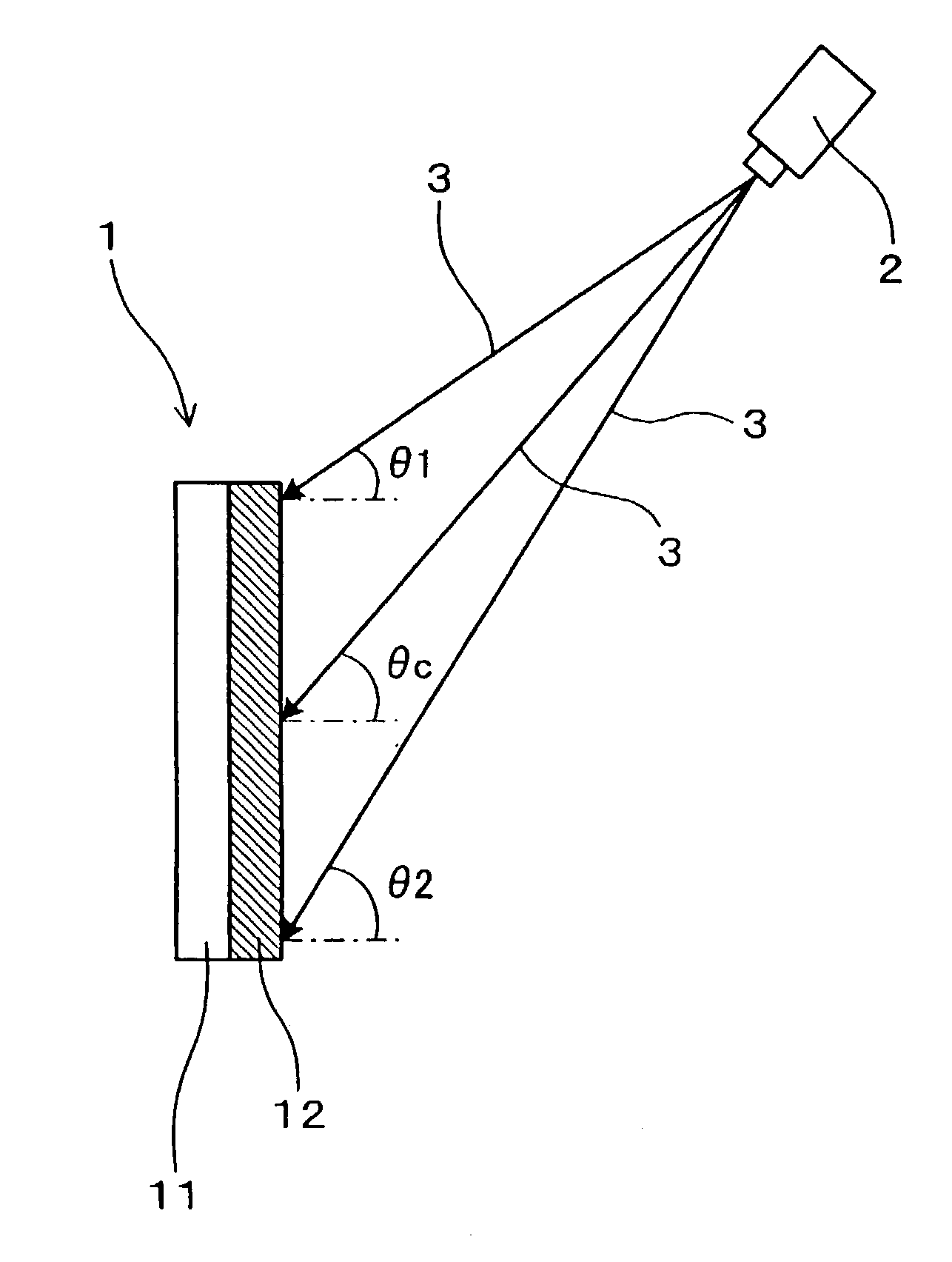
[0101] The holographic screen 1, as shown in FIG. 1, displays an image by diffracting and dispersing an image beam 3 projected by an image projector 2.
[0102] The holographic screen 1 has a main hologram 11 and a directional dispersion hologram 12 disposed on the image projector 2 side of the main hologram.
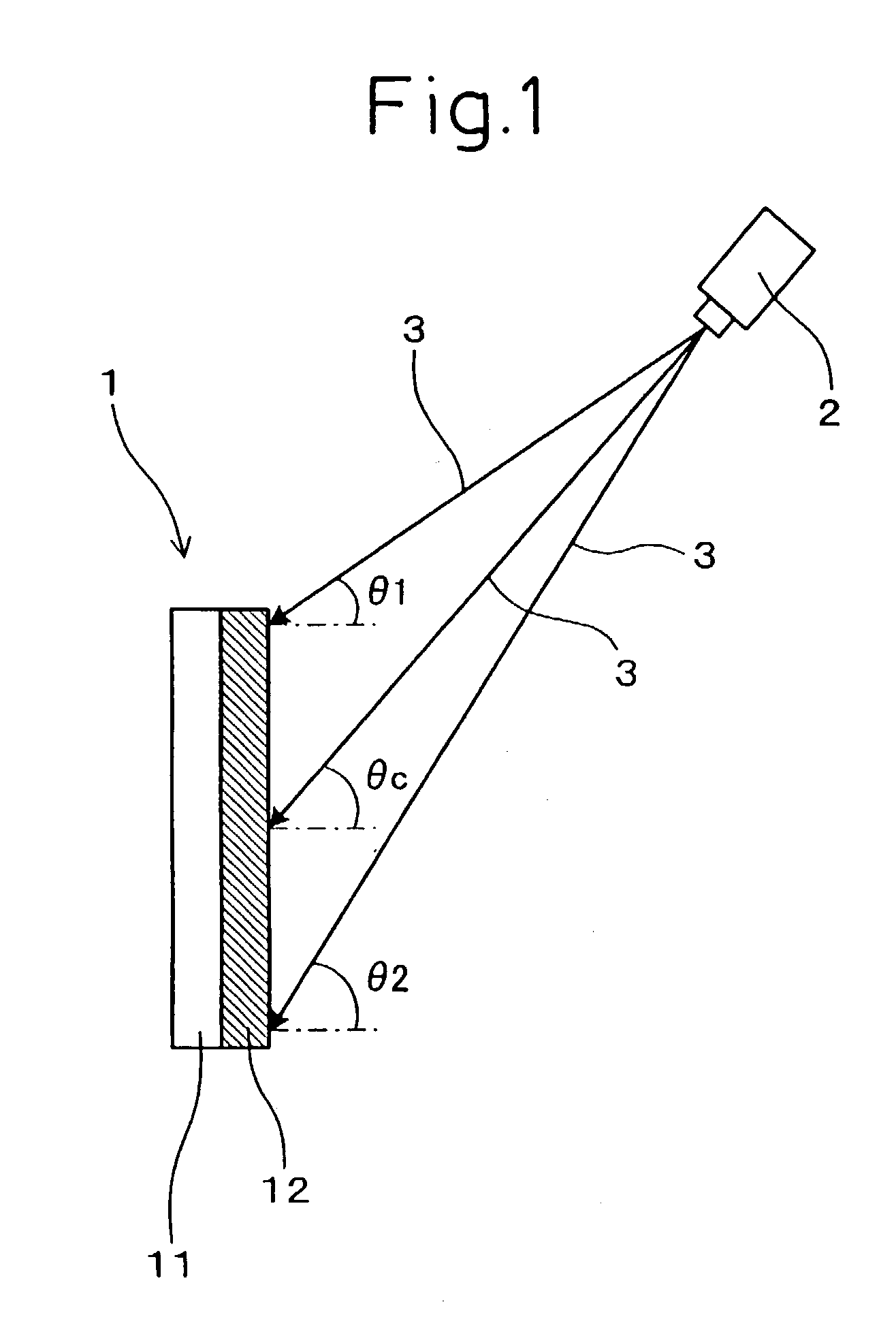
[0103] The main hologram 11, as shown in FIG. 2, diffracts and disperses the image beams 3 incident from an upward angle into diffraction beams 36.
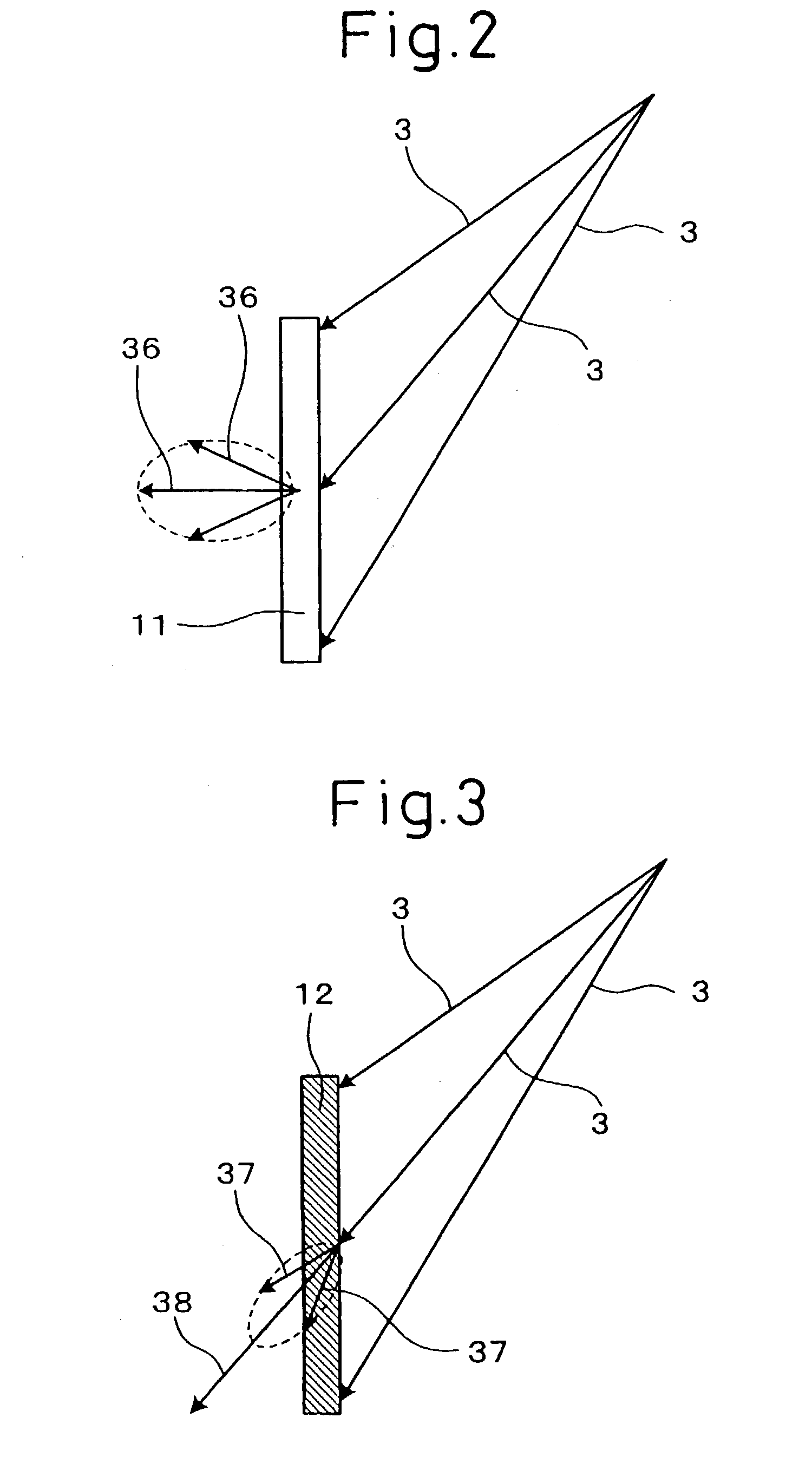
[0104] The directional dispersion hologram 12, as shown in FIG. 3, transmits part of the image beams 3 by dispersing them within a predetermined angle range centered on the direction of incidence of the image beams 3, and directly transmits the other part of the image beams 3. That is, part of the image beams 3 becomes dispersed transmitted beams 37, and the other part becomes a directl...
second embodiment
[0135] Second Embodiment
[0136] This embodiment, as shown in FIGS. 7 to 11, is a first example of a manufacturing method of the holographic screen 1 explained in the first embodiment.
[0137] The directional dispersion hologram 12 forming the above holographic screen is manufactured as described below.
[0138] That is, firstly, as shown in FIG. 7, a photosensitive material 4 and diffuser 5 are superposed. Then, a reference beam 6 is made incident thereon at a predetermined angle .theta.d to the normal from the diffuser side, and is transmitted through the diffuser 5 and diffused to become a diffused beam. The photosensitive material 4 is then exposed to the diffused beam.
[0139] Although the above predetermined angle .theta.d is preferably substantially the same as the angle of incidence .theta.c of the image beam (shown in FIG. 1), it can somewhat deviate therefrom.
[0140] The above diffuser 5, as shown in FIGS. 8 to 10, is formed from a directional dispersion film 50 that diffuses only i...
third embodiment
[0151] Third Embodiment
[0152] The present embodiment, as shown in FIG. 12, is a second example of a manufacturing method of the holographic screen 1 disclosed in the first embodiment.
[0153] In manufacturing the directional dispersion hologram 12 forming the holographic screen 1, the diffuser recorded on the photosensitive material 4 is ground glass 51. Namely, ground glass 51 is used in place of the directional dispersion film 50 (Lumisty MFY-2555) used in the second embodiment.
[0154] The exposure optical system has a structure wherein the photosensitive material 4 and the ground glass 51 are superposed via a transparent glass sheet 71, and the reference beam 6 is made incident thereon from an oblique direction.
[0155] Dispersed beams generated by transmitting the reference beam through the ground glass 51 interfere with each other on the surface of the photosensitive material 4 to expose the photosensitive material 4. The directional dispersion hologram 12 is thereby formed.
[0156] E...
PUM
 Abstract
Description
Claims
Application Information