Communication interface system for locally analyzing computers

a technology of communication interface and computer, applied in the field of communication interface system for locally analyzing computers, can solve the problems of limited input/output capability, inconvenient or cost-effective to have a monitor for each system, and insufficient room for monitors and other peripheral devices such as mouse and keyboard

Inactive Publication Date: 2003-10-09
ZAUDTKE STEPHEN M +2
View PDF36 Cites 55 Cited by
  • Summary
  • Abstract
  • Description
  • Claims
  • Application Information

AI Technical Summary

Problems solved by technology

For larger networks with several servers, it is not always convenient or cost effective to have a monitor for each system, or even to supply a single common monitor.
For example, for network configurations including one or more servers mounted on a rack, there may be insufficient room for a monitor and other peripheral devices such as a mouse and keyboard.
The LED design provides limited Input / Output (I / O) capability, is awkward to use, and provides limited capability, as only a particular subset of management information is available due in part to limited display capability.
An existing IMD is relatively expensive and consumes a large amount of real estate on the front bezel.
The case of the IMD is excessively large for the new dense server designs, and cannot be included on some designs.
For example, cooling requirements may often preclude the use of a large diagnostic display that consumes a substantial amount of front bezel space.
It is possible to reduce the size and capabilities of the IMD, but reducing functional capabilities is not always desired or practicable.
A configuration with a substantial number of displays are often utilized only in the exception case, such as when indicating the need for attention during fault conditions, and thus are often under-utilized during normal operations.

Method used


Image

  • Communication interface system for locally analyzing computers
  • Communication interface system for locally analyzing computers
  • Communication interface system for locally analyzing computers

Examples


Embodiment Construction

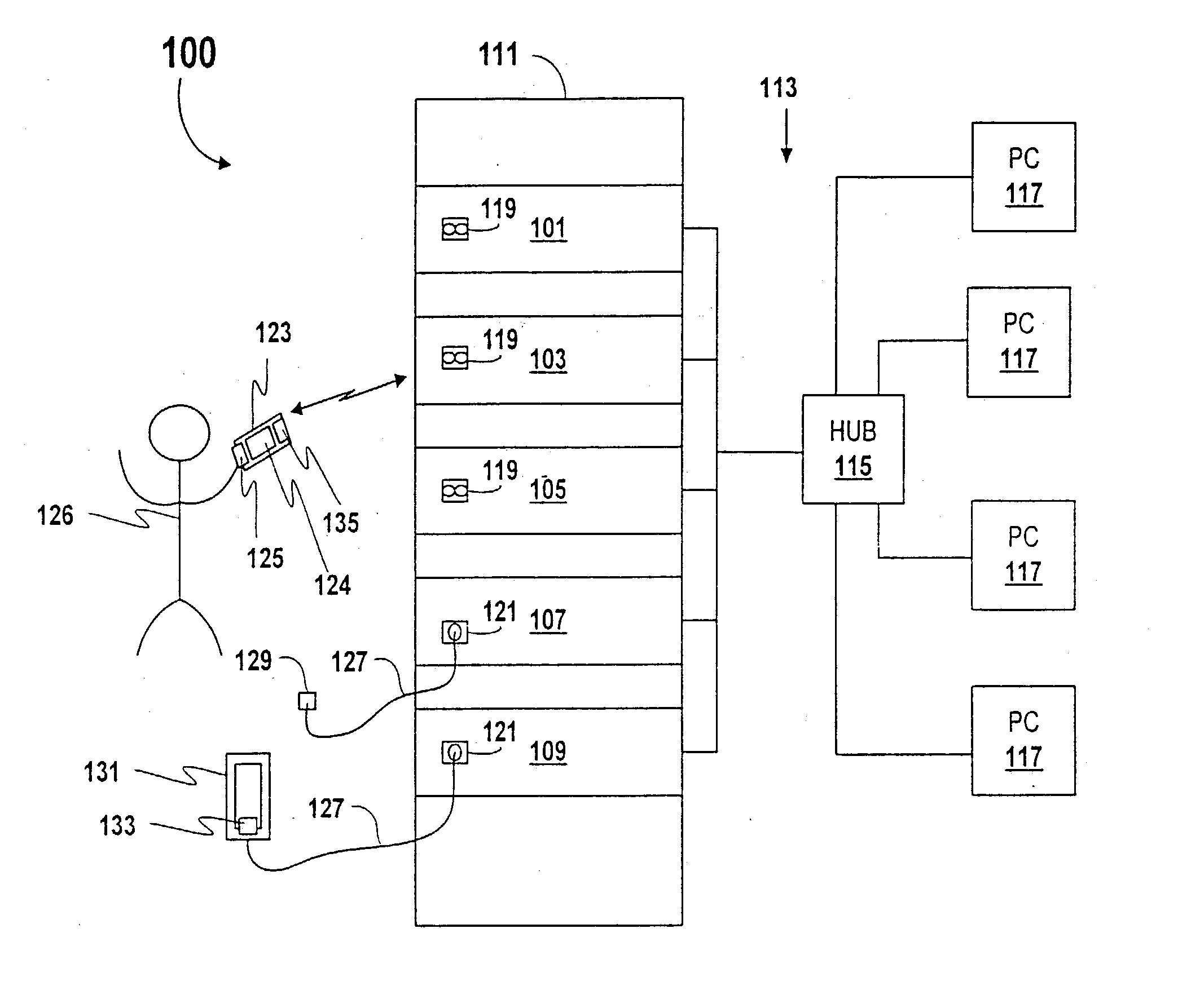
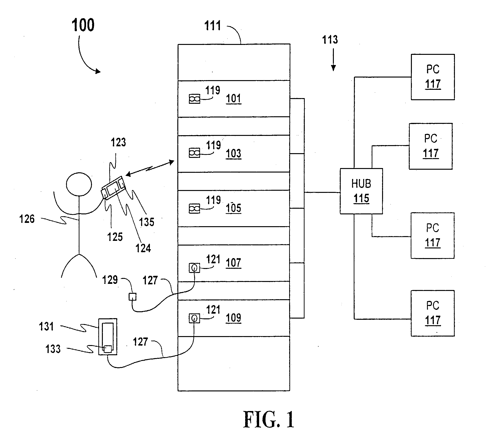
[0032] FIG. 1 is a simplified block diagram of an exemplary network system 100 that is used to illustrate a communication interface system according to an embodiment of the present invention. Although the communication interface system is useful and illustrated in a network configuration, it is understood that the present invention is not limited to network configurations and may be utilized in any type of computer system, including a standalone computer system. One or more server computers 101, 103, 105, 107, 109, etc. are coupled to a network 113, such as a local area network (LAN) or the like, for servicing one or more computer systems (PCs) 117. In the embodiment shown, the network 113 is implemented with a HUB 115, such as a repeater or switch device or the like, that is coupled to each server computer 101-109 and to each of the PCs 117 in a star configuration. Each of the server computers 101-109 and the PCs 117 include an appropriate network card or NIC or the like (not shown...


PUM


Abstract

A communication interface system including a computer and a handheld device that communicate with each other via respective communication ports. The computer communication port is a serial port or an infrared transceivers conveniently located on the front bezel of the computer. In serial embodiments, the computer executes the appropriate driver and interface applications to enable transfer of information to the handheld device. In infrared embodiments, the computer includes a microcontroller, an I<2>C bus and memory, where the microcontroller implements infrared communication protocol. Alternatively, the computer may further include a management processor that either replaces or cooperates with the microcontroller. Auxiliary power may enable handheld communications when the computer is shut down. The handheld device interfaces with the computer communication port to retrieve and display the status information. The handheld device effectively replaces external LCD health status hardware that typically consumes valuable space on the front bezel of the computer. The handheld device may further replace traditional input/output (I/O) devices, such as a keyboard, a mouse, a monitor, a disk drive, etc. For example, the handheld device may be utilized to monitor and control boot up operations of the computer, such as displaying boot up information or otherwise executing setup or, diagnostic routines.

Description

[0001] The present invention relates to computer management and diagnostics, and more particularly to a system and method for retrieving, displaying and controlling information of a computer by a handheld or portable device or the like via a communication interface.DESCRIPTION OF THE RELATED ART[0002] It is often desired or even necessary to monitor certain parameters of a computer system to determine its status or to identify certain error conditions. This is particularly true for a server on a network. System administrators of a network, for example, must typically monitor the operation of one or more computers operating as servers of the network to determine and identify critical errors and operating parameters. One or more server systems are typically coupled to a local area network (LAN) or wide area network (WAN) or the like to serve a corresponding plurality of client computer systems. In more sophisticated configurations, the servers are equipped with management capabilities...

Claims


Application Information

Patent Timeline
Patent Type & Authority Applications(United States)
IPC IPC(8): G06F3/00G06F11/273G06F13/12
CPCG06F11/0709H04L67/36G06F11/2294G06F11/0748H04L67/75
Inventor ZAUDTKE, STEPHEN M.BROWN, ANDREWHASCALL, DOUGLAS R.
Owner ZAUDTKE STEPHEN M
Why Eureka
Try Eureka