Redundant field drive for an electric machine

a technology of redundancy field and electric machine, which is applied in the direction of emergency power supply arrangement, electric generator control, dynamo-electric converter control, etc., can solve problems such as loss of generated power

Inactive Publication Date: 2003-10-30
DELPHI TECH IP LTD
View PDF9 Cites 8 Cited by
  • Summary
  • Abstract
  • Description
  • Claims
  • Application Information

AI Technical Summary

Benefits of technology

0004] Disclosed herein is an electric power generating system comprising: an alternator and a voltage regulator, the voltage regulator including a normal field control and a redundant field control, and a selection apparatus for selecting between the normal field control and the redundant field control.

Problems solved by technology

Unfortunately, certain conditions and faults (e.g., the loss of the main clock, power supply or interconnection and the like) may occur within the voltage regulators that result in completely disabling the output to the field coil and thereby resulting in loss of generated power.

Method used


Image

  • Redundant field drive for an electric machine
  • Redundant field drive for an electric machine
  • Redundant field drive for an electric machine

Examples


Embodiment Construction

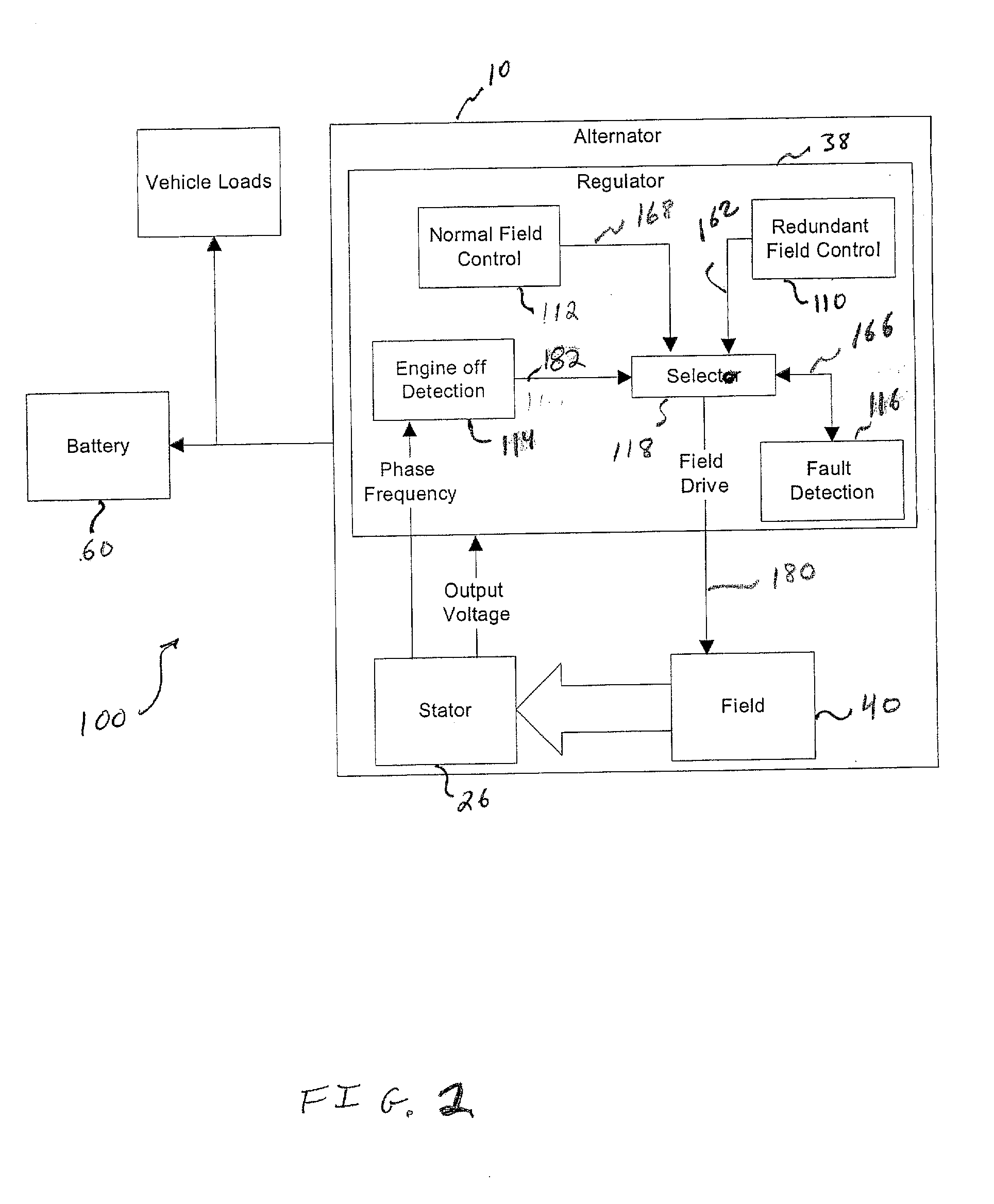
[0013] Disclosed herein in an exemplary embodiment is a redundant control algorithm configured to maintain a fixed set-point voltage for a vehicle power system even when certain faults occur that would otherwise result in loss of generator system operation. More particularly, in an exemplary embodiment a circuit is implemented that monitors the input system voltage (also denoted B.sup.+ in FIGS. 2 and 3), and creates an asynchronous (e.g., not linked to any clock or clocking in the control system) control command to result in vehicle power system response with a limit cycle around a fixed voltage set point. This allows the alternator to continue to generate power and the battery to continue to charge as needed, and yet prevents undercharging / overcharging the battery. It should be appreciated that generally in the art, alternator refers to an alternating current electric machine, while generator often refers to an electric machine with a direct current output (often as a function of ...


PUM


Abstract

An electric power generating system comprising: a generator including an alternator and regulator, the regulator including a normal field control and a redundant field control with a default field command and a selector for selecting between the normal field control and the redundant field control. Further disclosed, is a method of providing excitation to an alternator, comprising: receiving a field default signal indicative of an inoperative normal field control and a normal field command responsive to the normal field control, indicative of a desired duty cycle command to a field coil of an alternator. The method further includes determining if a supply voltage is greater than a selected value and formulating a default field command; transmitting a field drive responsive to the default field command to a field coil of the alternator if the field default signal is asserted.

Description

[0001] This invention relates to automotive electric generators or alternators. In many systems, the generator includes an alternator and a voltage regulator. Often the voltage regulator (hereinafter regulator) is integral with the alternator, but not necessarily so. The regulator controls the output voltage of the alternator to a calibrated voltage set point. The voltage is controlled by a regulation scheme, which adjusts the duty cycle on the rotor winding (often called the field or field coil) of the alternator. The output of the alternator is directly related to the duty cycle of the field coil, and the rotational speed of the rotor. The regulator also establishes a desired system voltage (called a set-point voltage) that the voltage regulator attempts to maintain. This set-point voltage may be based on temperature, a pulse width modulated (PWM) based customer input, or a serial data link customer input.[0002] For normal operation, when the actual system voltage (for example, vo...

Claims


Application Information

Patent Timeline
Patent Type & Authority Applications(United States)
IPC IPC(8): H02P9/14H02P9/48
CPCH02P9/48H02P9/14
Inventor HOCKEN, LARY ROBERTANDERSON, STEPHEN WAYNE
Owner DELPHI TECH IP LTD
Why Eureka
Try Eureka