Method for on-line testing of a light emitting panel

a technology of light-emitting panels and online testing, which is applied in the direction of optical apparatus testing, lighting and heating apparatus, instruments, etc., can solve the problems of high cost, high end product cost, and high cost of production process and ultimately final plasma display

Inactive Publication Date: 2003-11-06
LEIDOS
View PDF99 Cites 6 Cited by
  • Summary
  • Abstract
  • Description
  • Claims
  • Application Information

AI Technical Summary

Problems solved by technology

Using ITO, however, has several disadvantages; for example, ITO is expensive and adds significant cost to the manufacturing process and ultimately the final plasma display.
The sealing of the outer edges of the parallel plates and the introduction of the plasma-forming gas are both expensive and time-consuming processes, resulting in a costly end product.
In addition, it is particularly difficult to achieve a good seal at the sites where the electrodes are fed through the ends of the parallel plates.
This can result in gas leakage and a shortened product lifecycle.
Another disadvantage is that individual pixels are not segregated within the parallel plates.
As a result, gas ionization activity in a selected pixel during a write operation may spill over to adjacent pixels, thereby raising the undesirable prospect of possibly igniting adjacent pixels.
While this type of display structure decreases spillover, spillover is still possible because the pixels are not

Method used


Image

  • Method for on-line testing of a light emitting panel
  • Method for on-line testing of a light emitting panel
  • Method for on-line testing of a light emitting panel

Examples


Embodiment Construction

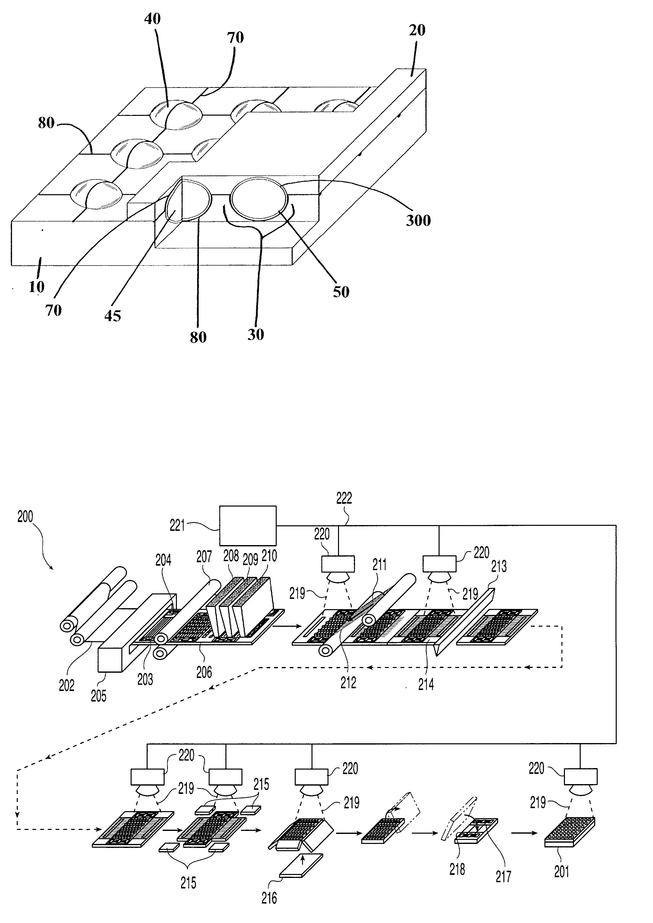
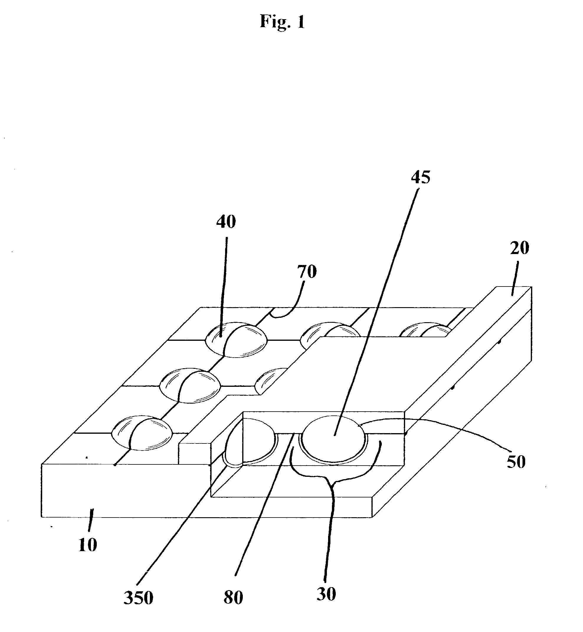
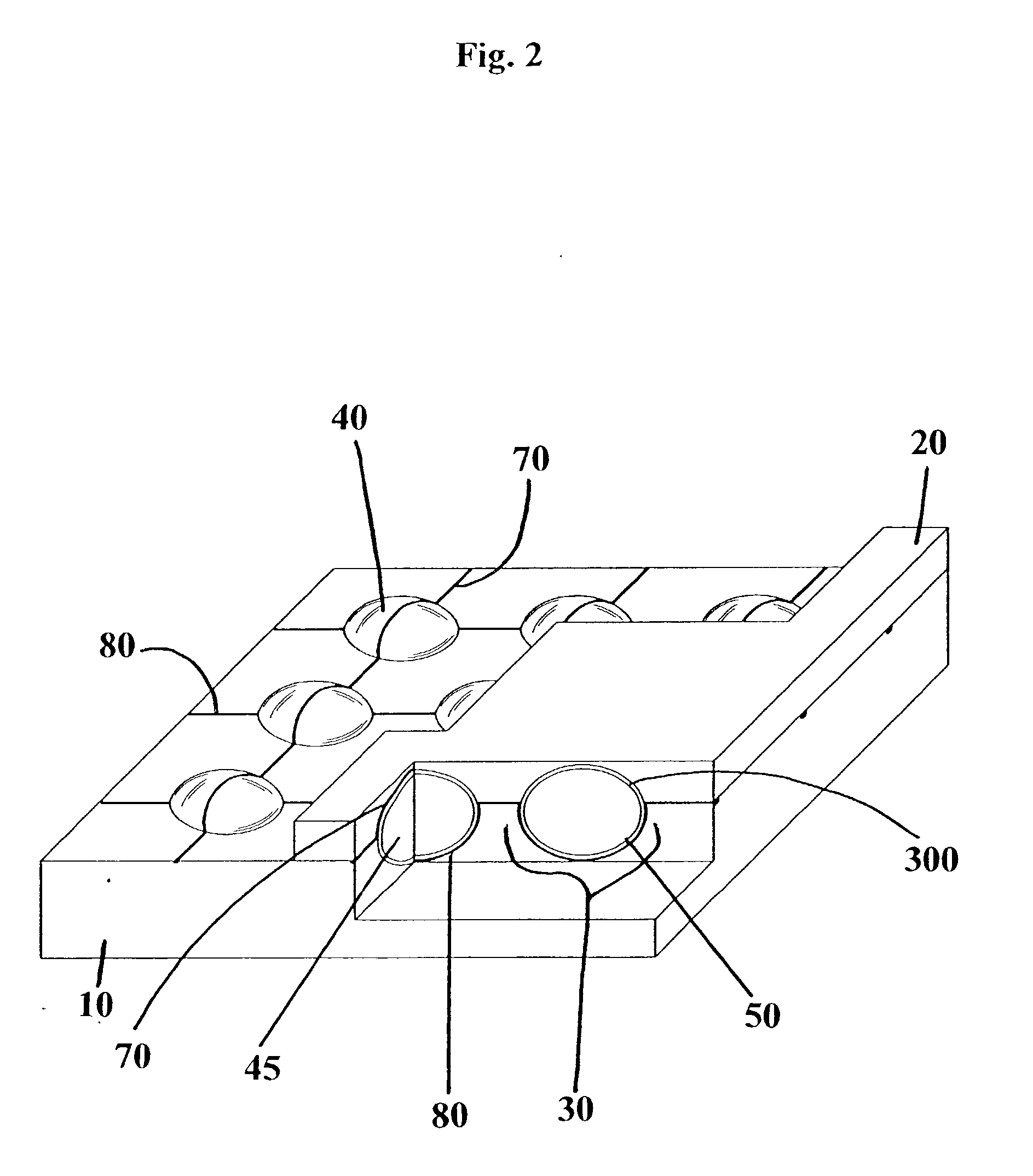
[0055] As embodied and broadly described herein, the preferred embodiments of the present invention are directed to a novel light-emitting panel. In particular, preferred embodiments are directed to light-emitting panels and a method for testing light-emitting panels and the components therein.

[0056] FIGS. 1 and 2 show two embodiments of the present invention wherein a light-emitting panel includes a first substrate 10 and a second substrate 20. The first substrate 10 and the second substrate 20 may be made from silicates, polypropylene, quartz, glass, any polymeric-based material or any material or combination of materials known to one skilled in the art. The first substrate 10 and second substrate 20 may both be made from the same material or from a different material. Additionally, the first and second substrates 10,20 may be made of materials that dissipate heat from the light-emitting panel. In a preferred embodiment, the first and second substrates 10,20 are made from material...


PUM


Abstract

A method of testing a light-emitting panel and the component parts therein including an assembled web containing light-emitting micro-components is disclosed. The method utilizes radiometric measuring devices disposed throughout a continuous fabrication process. Qualities of the components are measured so that product defects or process deficiencies can be corrected or eliminated.

Description

[0001] The following application is a Continuation-In-Part of Co-Pending U.S. application Ser. No. 09 / 697,498 filed Oct. 27, 2000.[0002] The entire disclosures of U.S. patent application Ser. Nos. 09 / 697,345, 09 / 697,346, 09 / 697,358, and 09 / 697,344 all of which were filed on Oct. 27, 2000 are hereby incorporated herein by reference. In addition, the entire disclosures of the following applications filed on the same date as the present application are hereby incorporated herein by reference: Method and Apparatus for Addressing Micro-Components in a Plasma Display Panel (Attorney Docket Number SAIC0026-CIP); Design, Fabrication, Testing and Conditioning of Micro-Components for Use in a Light-Emitting Panel (Attorney Docket Number SAIC0027-CIP); Liquid Manufacturing Process for Panel Layer Fabrication (Attorney Docket Number SAIC0029-CIP1); and Use of Printing and Other Technology for Micro-Component Placement (Attorney Docket Number SAIC0029-CIP2).[0003] 1. Field of the Invention[0004]...

Claims


Application Information

Patent Timeline
IPC IPC(8): G01M11/00G09G3/00G09G3/22H01J9/02H01J9/227H01J9/24H01J9/42H01J17/49
CPCG09G3/006G09G3/22H01J2217/492H01J11/18H01J17/49H01J9/42
Inventor WYETH, N. CONVERSGREEN, ALBERT M.GEORGE, E. VICTOR
Owner LEIDOS
Why Eureka
Try Eureka