

Wide-angle lens
A wide-angle lens and lens technology, applied in the field of camera lenses, can solve the problems of unusable, distortion, and large structure size and cannot be applied to head-mounted VR, etc., and achieve the effects of eliminating aberration, reducing focus movement, and improving optical performance.
- Summary
- Abstract
- Description
- Claims
- Application Information
AI Technical Summary
Problems solved by technology
Method used
Image

Examples
Embodiment 1
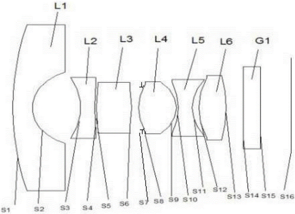
[0058] see Figure 1a to Figure 1e , is a kind of wide-angle lens provided in the first embodiment of the present invention. From the object side to the imaging surface, it includes a meniscus-shaped first lens L1 with negative refractive power and a concave surface facing the imaging surface, and a second lens with negative refractive power. Lens L2, the third lens L3 with positive refractive power, the fourth lens L4 with positive refractive power and convex surfaces on both sides, and the fifth lens L5 with negative refractive power and concave surfaces on both sides, with positive refractive power And the sixth lens L6 whose both sides are convex, the diaphragm S7 arranged between the third lens L3 and the fourth lens L4, and the filter arranged between the sixth lens L6 and the imaging surface In the light sheet G1, each lens is a plastic aspheric lens.
[0059] In this embodiment, the curvature radius of the S2 surface of the first lens L1<the curvature radius of the S3...
Embodiment 2
[0069] see Figure 2a to Figure 2e , is a wide-angle lens provided in the second embodiment of the present invention. The structure of the wide-angle lens in this embodiment is roughly the same as that of the wide-angle lens in the first embodiment. The difference is that the second lens near the object side One side is convex and the side near the imaging surface is concave, and the side of the third lens near the object side is concave and the side near the imaging surface is convex.
[0070] In this embodiment, the curvature radius of the S4 surface of the second lens<the curvature radius of the S2 surface of the first lens<the curvature radius of the S6 surface of the third lens<the curvature radius of the S1 surface of the first lens Radius of curvature<radius of curvature of surface S5 of the third lens<radius of curvature of surface S3 of the second lens.
[0071] In this embodiment, relevant parameters of each lens are shown in Table 2-1.
[0072] table 2-1
[0073]...
Embodiment 3
[0080] see Figure 3a to Figure 3e , is a kind of wide-angle lens provided by the third embodiment of the present invention. The structure of the wide-angle lens in this embodiment is roughly the same as that of the wide-angle lens in the first embodiment. The difference is that the third lens is close to the object side One side is concave and the side closer to the imaging plane is convex.
[0081] In this embodiment, the curvature radius of the S2 surface of the first lens<the curvature radius of the S4 surface of the second lens<the curvature radius of the S3 surface of the second lens<the curvature radius of the S6 surface of the third lens Radius of curvature<radius of curvature of surface S5 of the third lens<radius of curvature of surface S1 of the first lens.
[0082] In this embodiment, relevant parameters of each lens are shown in Table 3-1.
[0083] Table 3-1
[0084] Surface serial number
radius of curvature
thickness
Refra...
PUM
| Property | Measurement | Unit |
|---|---|---|
| Optical length | aaaaa | aaaaa |
| Field of view | aaaaa | aaaaa |
Abstract
Description
Claims
Application Information