RF filtered DC interconnect

a dc interconnect and filtering technology, applied in the field of rf filtered dc interconnect, can solve the problems of not tolerating a large tolerance variation in and/or requiring an additional wire bond

Inactive Publication Date: 2003-11-20
OL SECURITY LIABILITY CO
View PDF0 Cites 119 Cited by
  • Summary
  • Abstract
  • Description
  • Claims
  • Application Information

AI Technical Summary

Problems solved by technology

A challenge is to perform these functions in an RF environment to ensure clean performance, i.e., passing only the DC or control signals and attenuating all unwanted and / or interfering RF signals and digital switching signals that have some RF component to them.
These interconnects must be mechanically hard mounted to the housing floor using solder or epoxy to provide sufficient mechanical integrity and ensure good filter performance, and do not tolerate a large tolerance variation in and / or require an additional wire bond.

Method used


Image

  • RF filtered DC interconnect
  • RF filtered DC interconnect
  • RF filtered DC interconnect

Examples


Embodiment Construction

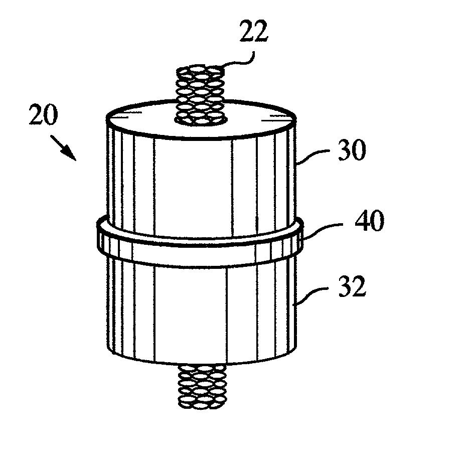
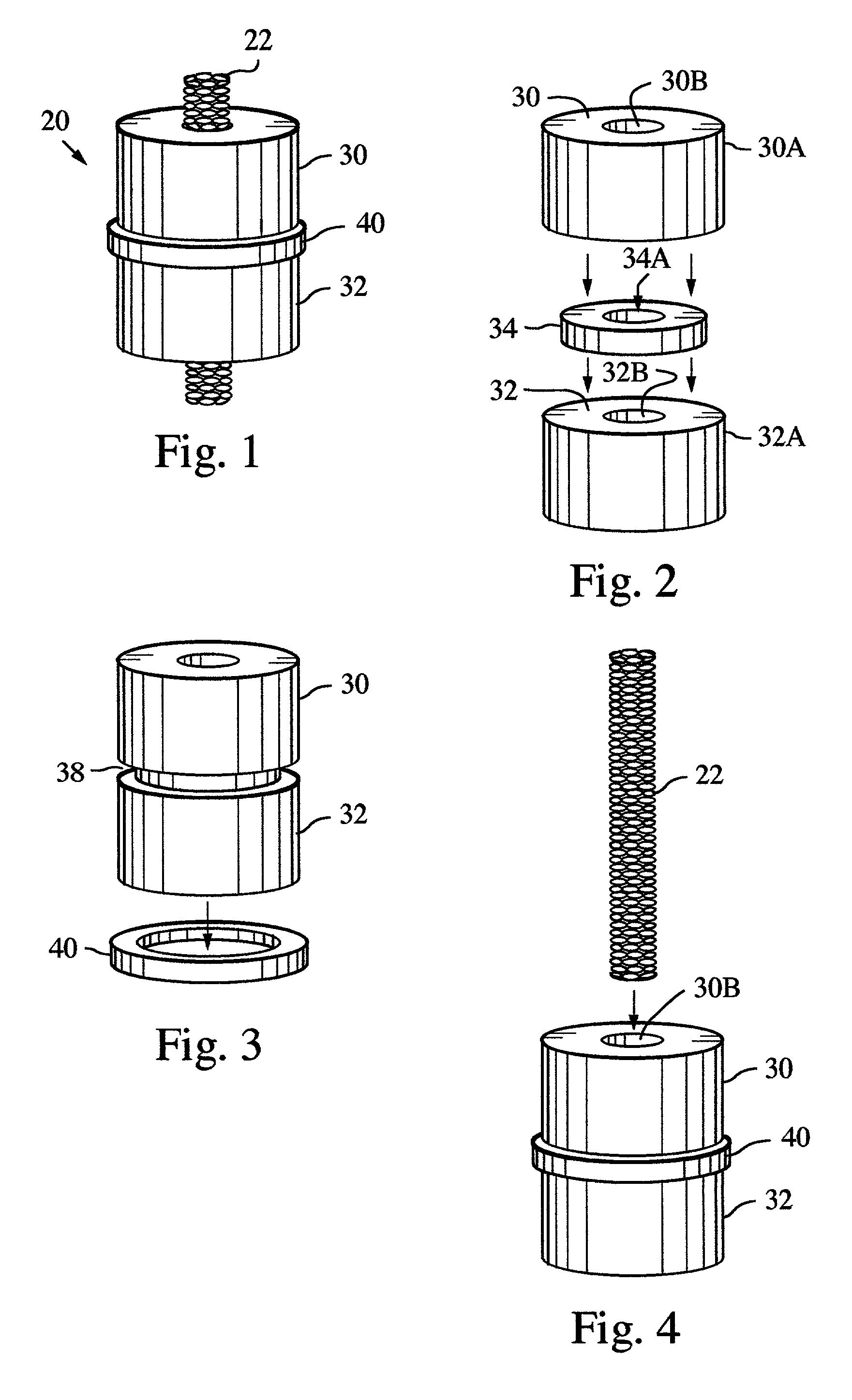
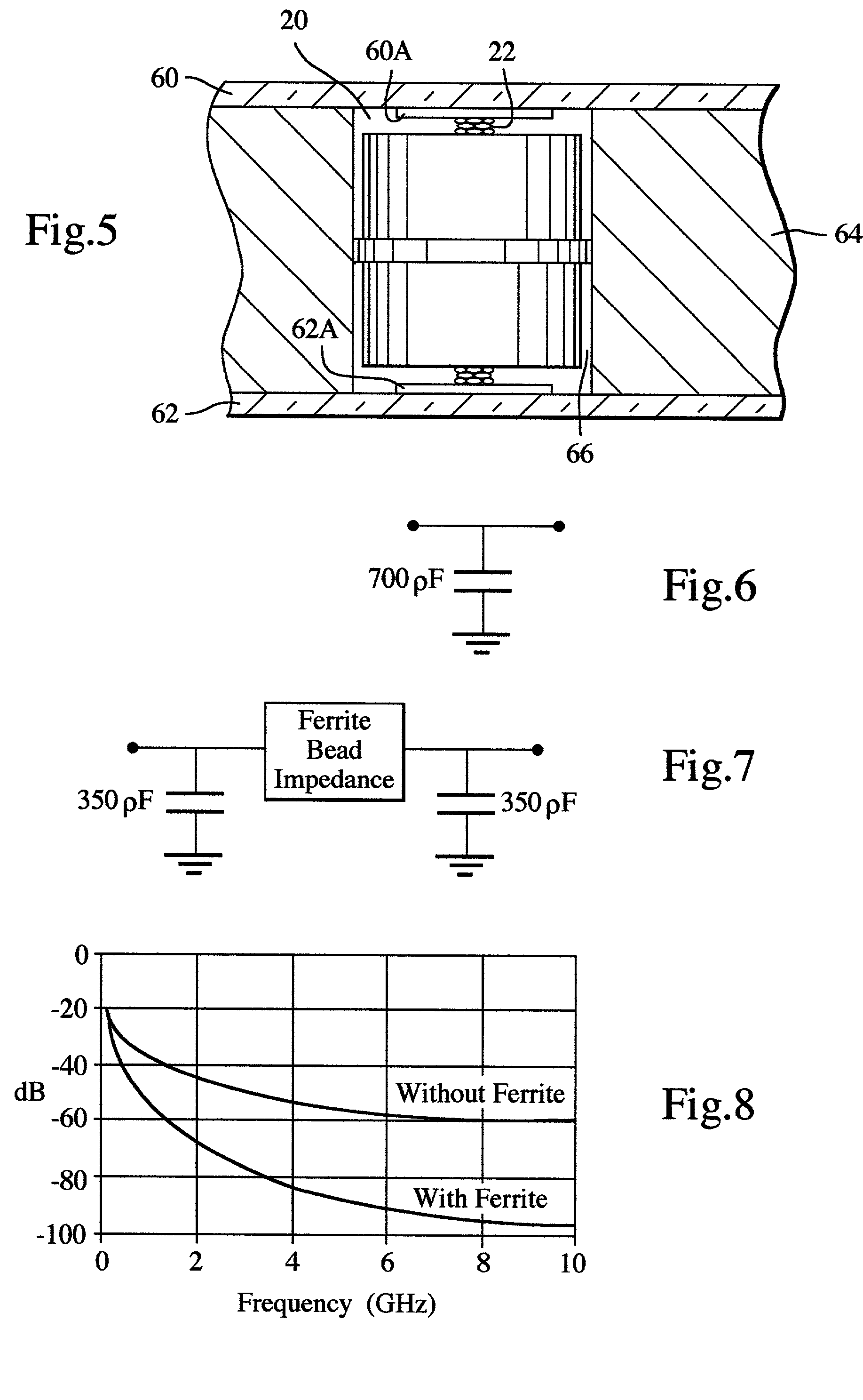
[0011] An embodiment of a filtered "button" DC interconnect between circuit boards employs a finely wound wire mesh imbedded within a series of dielectric and ferrite cylinders. An exemplary embodiment of a filtered button DC interconnect structure 20 is illustrated in FIGS. 1-4. The structure employs a finely wound wire mesh structure 22 imbedded within a series of dielectric and ferrite cylinders. FIG. 1 is an isometric view of the structure 20. FIGS. 2-4 are respective isometric partial exploded views, illustrating assembly of the structure and its constituent parts. The wire mesh interconnect 20 is captivated within the button structure to prevent movement and ensure proper contact with the mating surfaces. In addition, the interconnect serves as an RF filter by providing rejection of RF and microwave frequencies between the interconnected circuits 60, 62 (FIG. 5). The interconnect structure 20 accommodates wide assembly tolerances while maintaining excellent electrical contact....


PUM


Abstract

A filtered button DC interconnect employing a compressible conductor such as a finely wound wire mesh imbedded within a series of dielectric and ferrite cylinders. The compressible conductor is captivated within the series of dielectric and ferrite cylinders to ensure proper contact with mating surfaces of interconnected circuits. The interconnect serves as an RF filter by providing rejection of RF and microwave frequencies between the interconnected circuits.

Description

BACKGROUND OF THE DISCLOSURE[0001] DC interconnects are employed in RF systems to pass power and low speed control signals between separate circuit boards. A challenge is to perform these functions in an RF environment to ensure clean performance, i.e., passing only the DC or control signals and attenuating all unwanted and / or interfering RF signals and digital switching signals that have some RF component to them.[0002] Existing filtered interconnect schemes involve rigid pins and / or flanged connectors that are rigidly attached to a capacitive cylinder. These interconnects must be mechanically hard mounted to the housing floor using solder or epoxy to provide sufficient mechanical integrity and ensure good filter performance, and do not tolerate a large tolerance variation in and / or require an additional wire bond.SUMMARY OF THE DISCLOSURE[0003] A DC interconnect structure provides a DC interconnection between a first circuit board and a second circuit board. The interconnect struc...

Claims


Application Information

Patent Timeline
Patent Type & Authority Applications(United States)
IPC IPC(8): H03H1/00H05K1/02H05K1/14H05K3/32
CPCH03H1/0007H05K3/325H05K1/145H05K1/0243
Inventor ALLISON, ROBERT C.ROWLAND, JEROLD K.SHARPE, THOMAS M.
Owner OL SECURITY LIABILITY CO
Why Eureka
Try Eureka