Industrial two-layer fabric

a two-layer fabric and fabric technology, applied in the field of industrial two-layer fabric, can solve the problems of fiber carryback and splash, unresolved, opacity and paper strength degradation,

Active Publication Date: 2003-11-27
NIPPON FILCON
View PDF13 Cites 34 Cited by
  • Summary
  • Abstract
  • Description
  • Claims
  • Application Information

AI Technical Summary

Problems solved by technology

Such problems are more or less common problems among industrial fabrics and are not yet solved even at present.
Poor fiber supportability and paper removability lead to the occurrence of pin holes and cause degradation in opacity and deterioration in paper strength in addition to apparent problems.
They also lead to a fiber carryback and a splash and become serious problems from the viewpoint of operation.
However, the single-layer fabric has been becoming unable to keep up with an increasing mechanical load of a papermaking machine which has been increasingly faster.
Although the single-layer fabric has such advantages as a small thickness and good freeness, disadvantages caused by insufficient rigidity caused by its structure, such as poor formation, poor transportability and poor retention, have been becoming significantly noticeable.
However, it has a significant problem ascribable to the binding portions of the upper surface side warps.
That is, since the upper surface side warps serve as binding yarns, no warps are present in the upper layer fabric at the sites where the upper surface side warps go down to the lower surface side, so that local excessive dewatering occurs at the sites, fiber carrybacks, splashes and the like occur, and the sites appear as wire marks.
When marks in a lateral direction are remarkable, they even cause an adverse effect at the time of creping.
These problems are not yet solved.

Method used


Image

  • Industrial two-layer fabric
  • Industrial two-layer fabric
  • Industrial two-layer fabric

Examples


example 2

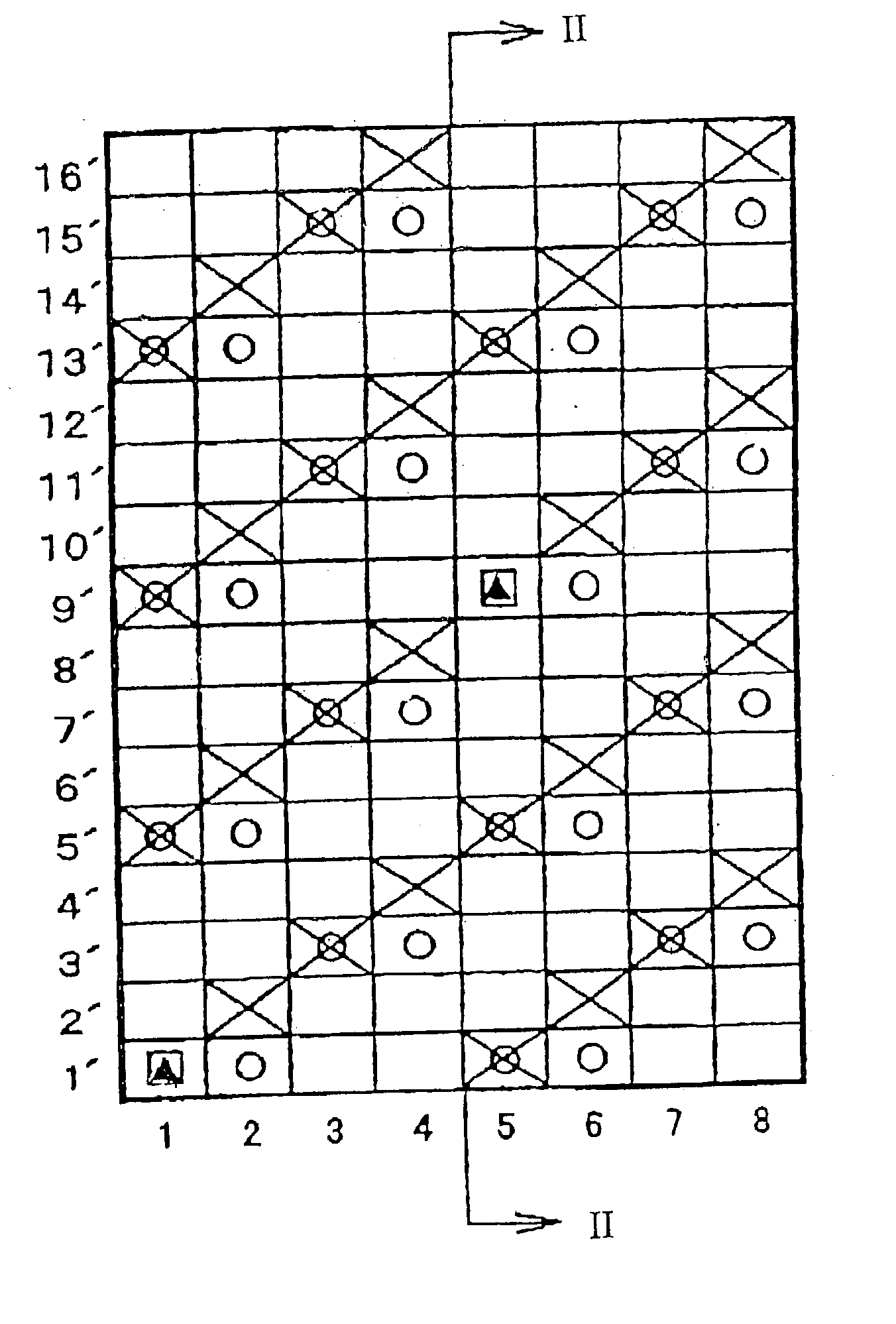
[0061] FIG. 3 is a diagram illustrating a repeating unit of Example 2 of the present invention. The placement of warps and wefts is the same as that in Example 1. Lower surface side wefts are placed underneath upper surface side wefts represented by odd numbers, and the upper layer fabric of the repeating unit has 24 wefts. The structures of the upper and lower layer fabrics are the same as those in Example 1. The upper layer fabric has a structure in which an upper surface side warp passes under three adjacent upper surface side wefts and then passes over an upper surface side weft. The lower layer fabric has a plain woven structure in which two adjacent lower surface side warps are formed parallel to each other. Example 2 is different from Example 1 in that while a warp serving as a binding yarn in each layer weaves and binds only one weft in the other layer in Example 1, the repeating unit of Example 2 has binding sites in which a binding portion formed by a warp passing over or ...

example 3

[0068] FIG. 5 is a diagram illustrating a repeating unit of Example 3 of the present invention. The repeating unit of Example 3 comprises 8 warps and 16 wefts. A warp serving as a binding yarn weaves a weft two times in a row so as to form biding portions. The proportion of warps provided as binding yarns is 1 / 2 of all upper surface side warps. An upper surface side warp has a structure that after the warp weaves two times upper surface side wefts from the upper surface side, it goes down to the lower surface side so as to weave two times lower surface side wefts from the lower surface side and then goes up to the upper surface side so as to weave two times upper surface side wefts from the upper surface side. Although the warp 1 / 3 structure of the upper layer fabric is unchanged, the proportion of the warps provided as binding yarns has been increased, so that a binding force has improved and adhesion between the upper and lower layer fabrics has become very good.

example 4

[0069] FIG. 6 is a diagram illustrating a repeating unit of Example 4 of the present invention.

[0070] The repeating unit of Example 4 is similar to but different from Example shown in FIG. 5 in that warps serving as binding yarns are shifted irregularly. The repeating unit of Example 4 has an advantage that diagonal wire marks are not conspicuous since binding portions are not continuous diagonally.


PUM


Abstract

An industrial two-layer fabric comprises an upper layer fabric having upper surface side warps and upper surface side wefts and a lower layer fabric having lower surface side warps and lower surface side wefts. The upper layer fabric and the lower layer fabric are bound at least one spot in a repeating unit where an upper surface side warp weaves a lower surface side weft without weaving an upper surface side weft which should have been woven by the upper surface side warp based on the fabric structure, and where a lower surface side warp weaves the upper surface side weft which should have been woven by the upper surface side warp, without weaving the lower surface side weft which should have been woven by the lower surface side warp.

Description

[0001] The present invention relates to industrial fabrics such as a papermaker's forming fabric, a fabric for producing a nonwoven fabric, a fabric used to remove or squeeze water out of sludge and the like, a belt for producing construction materials, and a conveyor belt. In particular, the present invention relates to a papermaker's fabric, particularly a fabric for producing tissues.DESCRIPTION OF RELATED ART[0002] Industrial fabrics which have been conventionally used include papermaker's fabrics such as a papermaker's forming fabric and a canvas, a fabric for producing a nonwoven fabric, a fabric used to remove or squeeze water out of sludge and the like, a belt for producing construction materials, a conveyor belt, and the like. These industrial fabrics run under tension in a longitudinal direction at the time of use. Hence, they must have dimensional stability so as to prevent contraction in a width direction and elongation from occurring. Further, they must also have postur...

Claims


Application Information

Patent Timeline
Patent Type & Authority Applications(United States)
IPC IPC(8): D03D3/04D03D11/00D04HD21F1/00D21F7/08
CPCD03D11/00Y10S162/90Y10S162/902D21F1/0036
Inventor NAGURA, HIROYUKIUEDA, IKUOFUJISAWA, SHIGENOBU
Owner NIPPON FILCON
Why Eureka
Try Eureka