Catheter systems and methods for placing bi-ventricular pacing leads

a bi-ventricular and pacing technology, applied in the field of catheters, can solve the problem of quite difficult access to the coronary sinus

Active Publication Date: 2003-12-11
BIOCARDIA
View PDF11 Cites 67 Cited by
  • Summary
  • Abstract
  • Description
  • Claims
  • Application Information

AI Technical Summary

Problems solved by technology

Access the coronary sinus is quite difficult.
Additionally, injection of contrast agent may help to visualize the venous system during placement, but the balloon catheter is no longer present to prevent the contrast agent from being quickly flushed from the site of interest.

Method used


Image

  • Catheter systems and methods for placing bi-ventricular pacing leads
  • Catheter systems and methods for placing bi-ventricular pacing leads
  • Catheter systems and methods for placing bi-ventricular pacing leads

Examples


Embodiment Construction

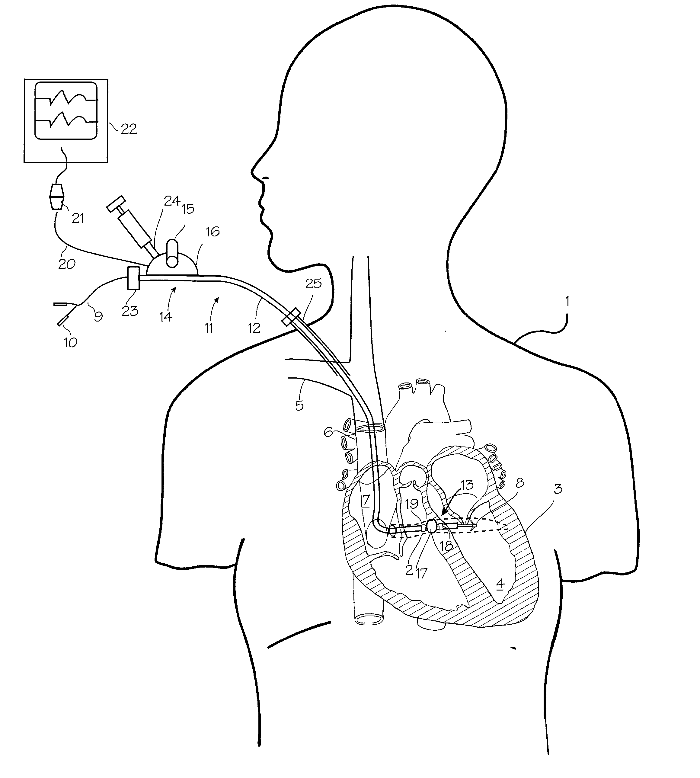
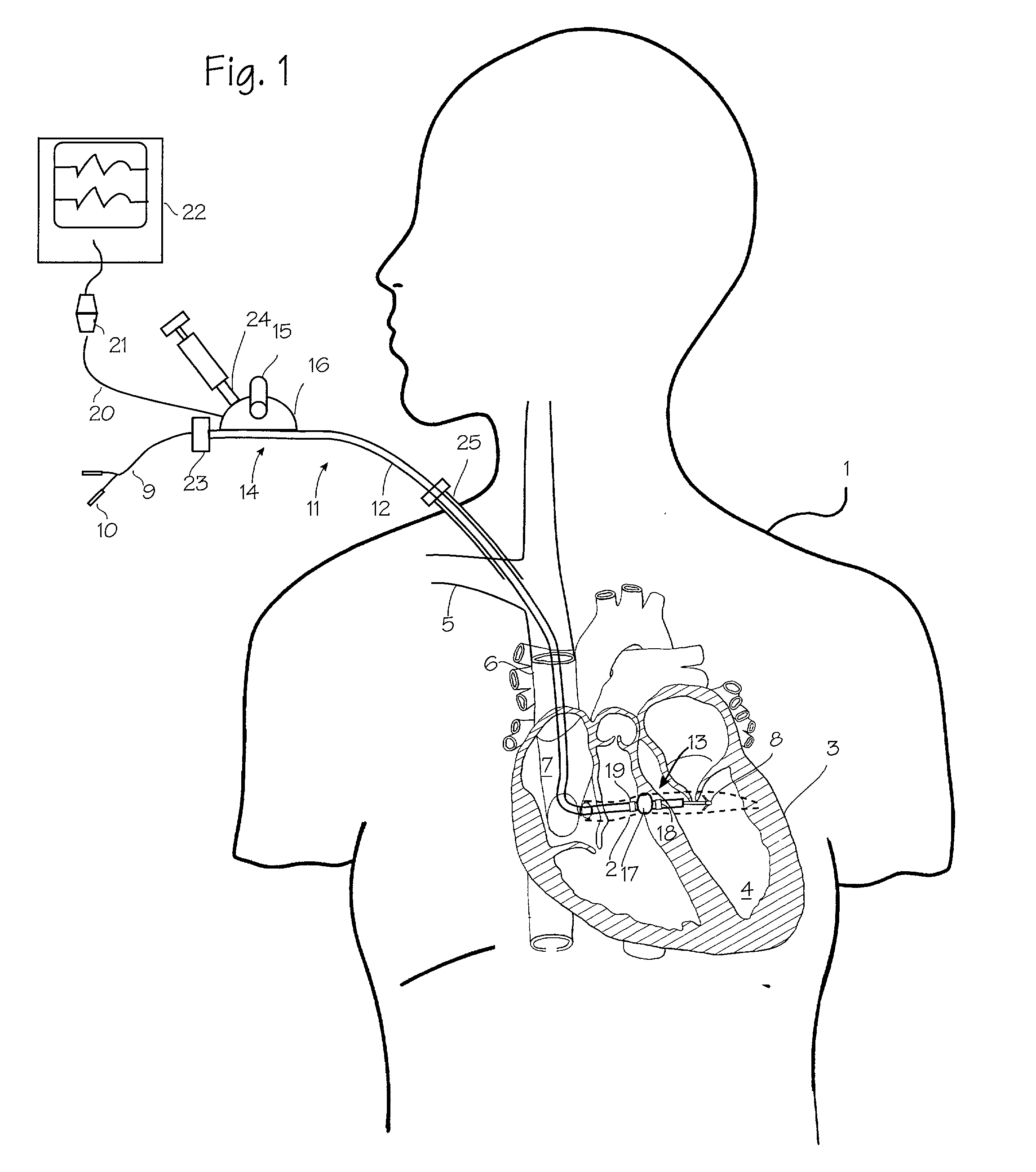
[0017] FIG. 1 illustrates an exemplary use of the catheter and method especially adapted for placement of devices in the human body. The patient 1 is undergoing a catheterization of the coronary sinus 2, which is the primary venous drainage vessel of the heart 3 in order to place a pacemaker lead into the left ventricle 4. Access to the coronary sinus is gained percutaneously, through the subclavian vein 5, the superior vena cava 6, and the right atrium 7. The goal of the catheterization is to place a pacemaker lead tip 8 into the left ventricle (or a location from which it can pace or stimulate the left ventricle), while temporarily leaving the pacemaker lead wire 9 itself in the tortuous venous pathway and leaving the pacemaker connectors 10 just outside the body. To achieve this, guide catheter 11 has been placed in the patient through the vasculature so that its distal tip is disposed within the coronary sinus. In the typical pacemaker lead placement, the connectors and the lead...


PUM


Abstract

A catheter system suitable for implanting pacemaker leads. A guide catheter is provided with steering capability, and the necessary steering components are modified to permit the catheter to be sliced during withdrawal, so that the proximal forced applied to the pacemaker lead is minimized and the lead is less likely to be dislodged.

Description

FIELD OF THE INVENTIONS[0001] The devices and methods described below relate to the catheters and methods of using catheters.BACKGROUND OF THE INVENTIONS[0002] Implanted cardiac pacemakers are used to detect abnormal heart rhythms and apply electrical shocks to the heart to keep the heart beating at a desired pace. They have typically been implanted with the leads attached to the right side of the heart (due to ease of placement), but bi-ventricular pacing has recently been developed to provide better pacing efficiency, heart output and patient quality of life. In bi-ventricular pacing, one lead is placed in electrical contact with the right ventricle, and a second lead is placed in electrical contact with the left ventricle. These leads are embedded into the heart, and their placement may be achieved surgically (for epicardial placement) and percutaneously (mostly through the right side of the heart and the venous system). Bi-ventricular pacing leads include one that is placed thro...

Claims


Application Information

Patent Timeline
Patent Type & Authority Applications(United States)
IPC IPC(8): A61N1/05
CPCA61N1/056A61N2001/0585A61N2001/0578
Inventor ROSENMAN, DANIEL C.MEAD, R. HARDWINALTMAN, PETER A.
Owner BIOCARDIA
Why Eureka
Try Eureka