Tubular electro-luminescent panel(s) light device

a technology of electroluminescent panel and light device, which is applied in the direction of lighting support device, lighting and heating apparatus, instruments, etc., can solve the problem of reducing brightness

Inactive Publication Date: 2003-12-18
CHIEN TSENG LU
View PDF8 Cites 122 Cited by
  • Summary
  • Abstract
  • Description
  • Claims
  • Application Information

AI Technical Summary

Problems solved by technology

Voskoboinik because the limited for the outer coil electrodes is too small and can not use bigger Coil because will cover the illumination areas and reduce the brightness.

Method used


Image

  • Tubular electro-luminescent panel(s) light device
  • Tubular electro-luminescent panel(s) light device
  • Tubular electro-luminescent panel(s) light device

Examples


Embodiment Construction

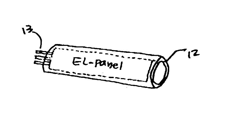
[0086] The current invention related Electro-luminescent panel(s) incorporated with tube-means with pre-designed wall thickness, color, transparency, softness to allow the said panel(s) can be follow the tube curvature to attach on the main objects. The improvement including there have a enough space to allow the panel(s) freely to move, change shape, bending, twisted within the tube so this will be able to attached some surface with pretty Neon, Flourescent tube light effects with desired function.

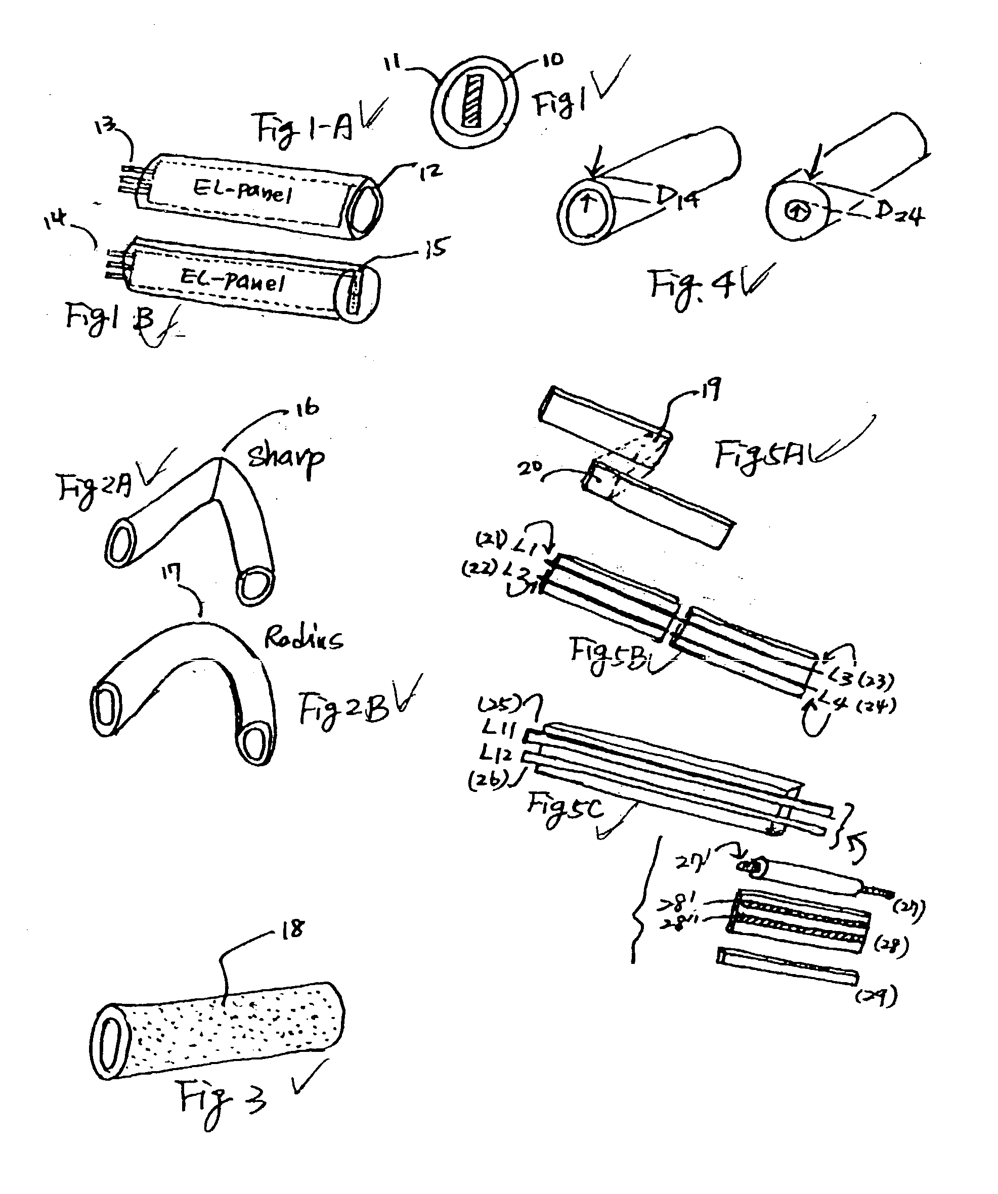
[0087] From FIG. (1) can see the tube-means (10) and inner narrow Electro-Luminescent panel (11) From FIG. (1A) can see the relation between Tube means (12) and panel (13). From FIG. (1B) can see the alternative tube means (15) which have the Open-groove can offer a space to install the Panel(s) (14) within the tube-means. The preferred tube means can be have desired design as above drawings as long as the Panel(s) can freely move within the space. The freely movement for panel(s) is a ve...


PUM


Abstract

A tubular Electro-Luminescent panel(s) light device offer a desired bending directions with super brightness basing on certain width of panel incorporated proper invertor system. The said panel(s) with much narrow width than tube means to allow the panel(s) can be bend at any direction and angle within the tube means to offer a desired light effects. The said panel(s) can be flat or twisted within the tube means which may have the desired colored, transparency, wall thickness, diameter, shape, length for requirement. The said device may incorporated with non-elastic means, magnetic means, tube holder, sensor means, Integrated circuit to add a lot of desired variety features.

Description

[0001] The tubular shape Electroluminescent (EL) light device as the U.S. Pat. No. 5,485,355 Voskoboinik et al. and[0002] U.S. Pat. No. 5,753,381 Feldman et al. and U.S. Pat. No. 5,711,594 Hay the tubular shape but both have its limitation including: too expensive for the process, too slow production speed, too limited for brightness, too difficult to make application etc.[0003] The current invention use a low-cost panel type of Electro-luminescent element to seal inside the of Tube shape will have super lower cost, simple production procedure, super brightness, easily to make any diameter which will overcome all the US prior arts.[0004] 1. The current invention teach a way to make a any diameter of tubular EL light device by simple process.[0005] 2. The current invention teach a way to solve the shape-angle while bending the Plastic tube.[0006] 3. The current invention teach a colored Plastic tube as a cosmetic purpose for a tubular EL light device.[0007] 4. The current invention t...

Claims


Application Information

Patent Timeline
Patent Type & Authority Applications(United States)
IPC IPC(8): A41D27/08A42B1/24A43B3/00A45C15/06B60Q1/26B60Q3/02G09F13/22
CPCA41D27/085F21S4/003A43B1/0036A43B3/0005A45C15/06B60Q1/26B60Q3/0289G09F13/22A42B1/244A43B3/001F21S2/00F21S4/001F21Y2105/00F21W2131/109A42B1/242F21S4/10F21S4/20B60Q3/78A43B3/36A43B3/34
Inventor CHIEN, TSENG-LU
Owner CHIEN TSENG LU
Why Eureka
Try Eureka