Optimized Y-branch design

a technology of y-branch and design, applied in the field of optical y-branch design, can solve the problems of state of the art y-branch losing a large amount of input energy, complex structure of optical network components,

Inactive Publication Date: 2004-01-15
INTEL CORP
View PDF7 Cites 23 Cited by
  • Summary
  • Abstract
  • Description
  • Claims
  • Application Information

AI Technical Summary

Problems solved by technology

The components used in optical networks are often complex structures, individually fabricated for specific applications of use.
Though complex overall, many of these components are formed of relatively simple individual optical devices combined to achieve complex functionality.
Both types of Y-branches have their limitations.
Unfortunately, state of the art Y-branches lose a sizeable amount of input energy due to limitations in device fabrication.
Even with such equipment, it is difficult to fabricate well-aligned and symmetric output waveguides especially at the smaller sizes.
Even if perfect alignment were to be achi...

Method used


Image

  • Optimized Y-branch design
  • Optimized Y-branch design
  • Optimized Y-branch design

Examples


example

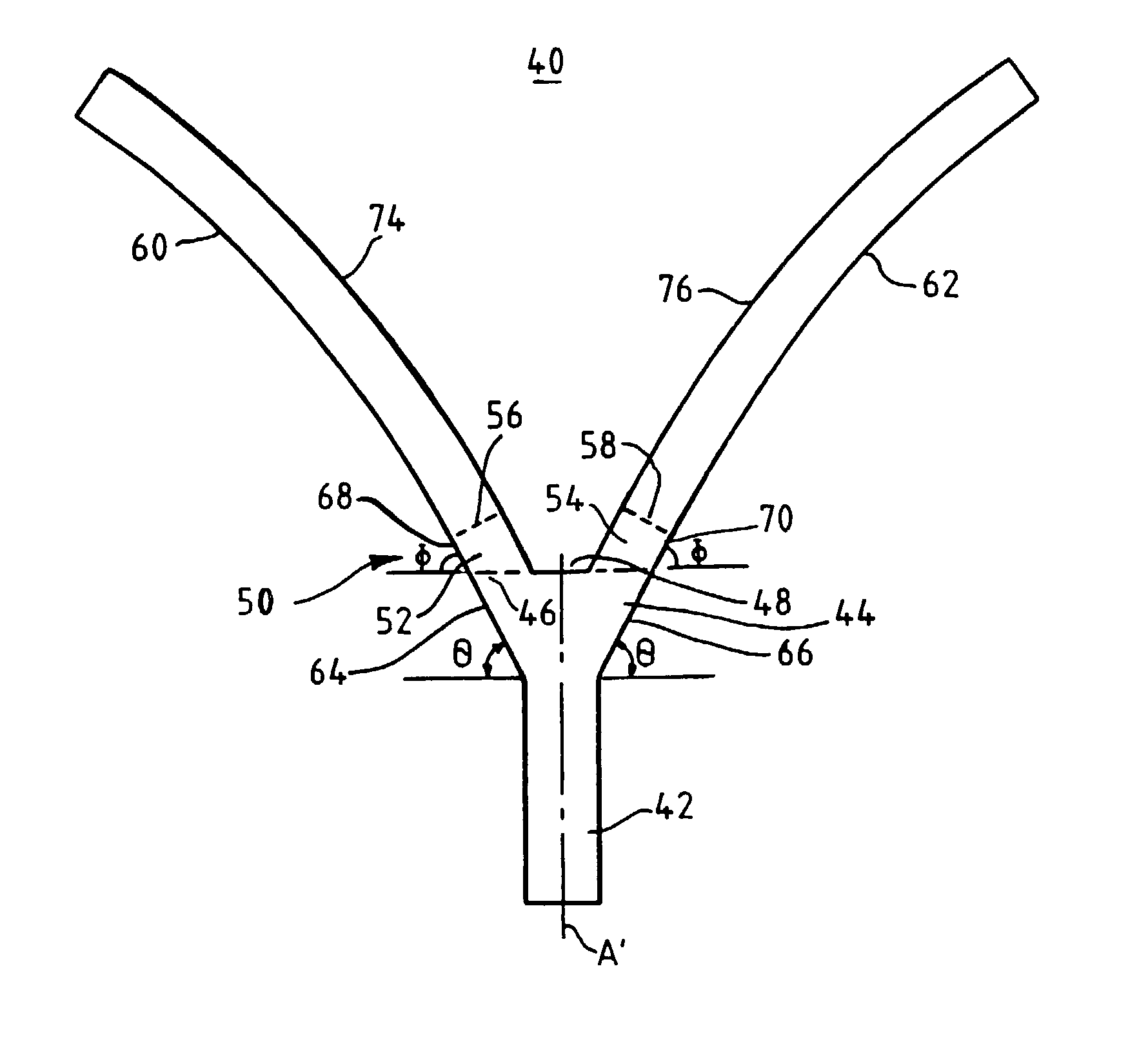
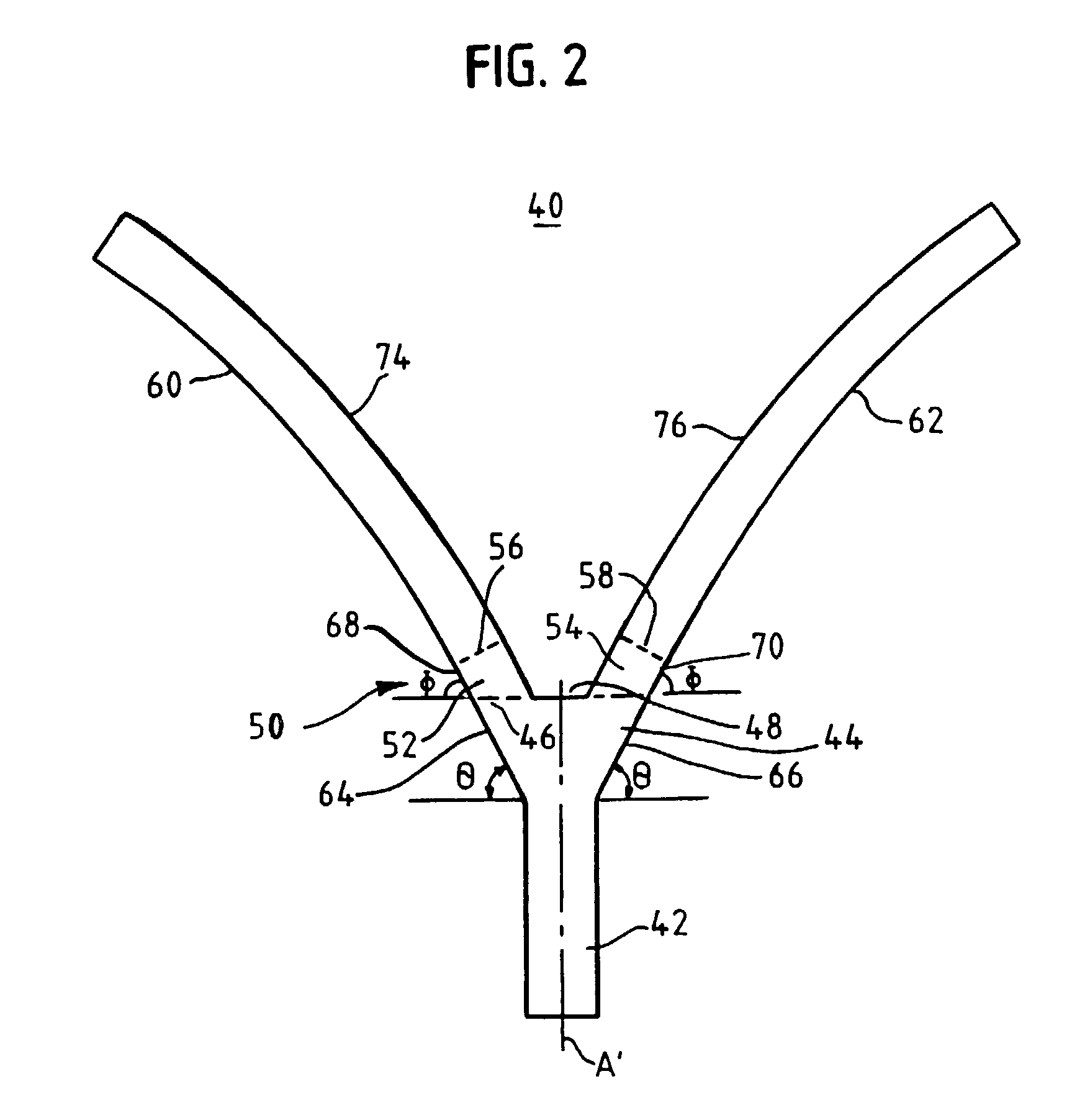
[0035] The branching waveguides and the input waveguide have rectangular cross-sections--taken orthogonal to the propagation axis of section 42--of a width of approximately 3 .mu.m and a height of approximately 3 .mu.m. The linear taper section 44 was approximately 75 .mu.m in length, measured along the propagation axis of the input waveguide and expanded to a width of 7 .mu.m at its maximum. An approximately 3.degree. taper angle (measured from the an input propagation axis) was used. Each straight section was approximately 20 .mu.m in length, as measured along the propagation axis starting at the gap position, and each straight section formed an angle with propagation axis of approximately 3.degree.. The gap had a width of between 0.5 to 1 .mu.m, and the radius of curvature on the portions of the branching waveguides at their trailing edges was approximately 1500 .mu.m.

[0036] In any event, the use of a straight section between the taper region and the output waveguides, as shown i...


PUM


Abstract

Optical structures useful in splitters, couplers, combiners, and switches are provided. An example optical structure has a Y-branch configuration that includes a linear taper segment and two branching waveguides. A straight section extends between the linear taper segment and the two branching waveguides to reduce losses during splitting/combining operation. The straight section may be used in Y-branch configurations having a blunt section, as well as configurations without a blunt section. Straight sections formed of a single segment and of multiple segments are shown, and the straight sections may be formed of substantially parallel outer walls or fanning-out outer walls. Further, in some embodiments, the branching waveguides form acute angles at the boundaries with the straight segment.

Description

[0001] The present invention relates generally to optical splitters and couplers and, more specifically, to such structures having a Y-branch configuration.BACKGROUND OF THE RELATED ART[0002] The components used in optical networks are often complex structures, individually fabricated for specific applications of use. Though complex overall, many of these components are formed of relatively simple individual optical devices combined to achieve complex functionality. Just as the advent of semiconductor logic gates facilitated the creation of the microprocessor, the development of simple optical devices performing functions such as coupling, splitting, and constructive / destructive interference allows system designers to form increasingly more complex optical circuits.[0003] Of the various basic optical structures, signal splitting / combining is one of the most important. Generally, splitting / combining is achieved through either direct or indirect coupling means. Indirect coupling, for ...

Claims


Application Information

Patent Timeline
IPC IPC(8): G02B6/125
CPCG02B6/125
Inventor JOHANNESSEN, KJETILLIU, ANSHENGJANSEN, HENNING
Owner INTEL CORP
Why Eureka
Try Eureka