Fuel cells with enhanced via fill compositions and/or enhanced via fill geometries

a technology of fuel cells and compositions, applied in the field of fuel cells, can solve the problems of limiting the durability of fuel cells, not being environmentally sound, and not being energy efficient in gas turbines and diesel generators

Inactive Publication Date: 2004-02-12
CORNING INC +1
View PDF7 Cites 75 Cited by
  • Summary
  • Abstract
  • Description
  • Claims
  • Application Information

AI Technical Summary

Problems solved by technology

However, gas turbines and diesel generators are not energy efficient nor are they environmentally sound.
Although the use of the flat silver-palladium e...

Method used


Image

  • Fuel cells with enhanced via fill compositions and/or enhanced via fill geometries
  • Fuel cells with enhanced via fill compositions and/or enhanced via fill geometries
  • Fuel cells with enhanced via fill compositions and/or enhanced via fill geometries

Examples


first embodiment

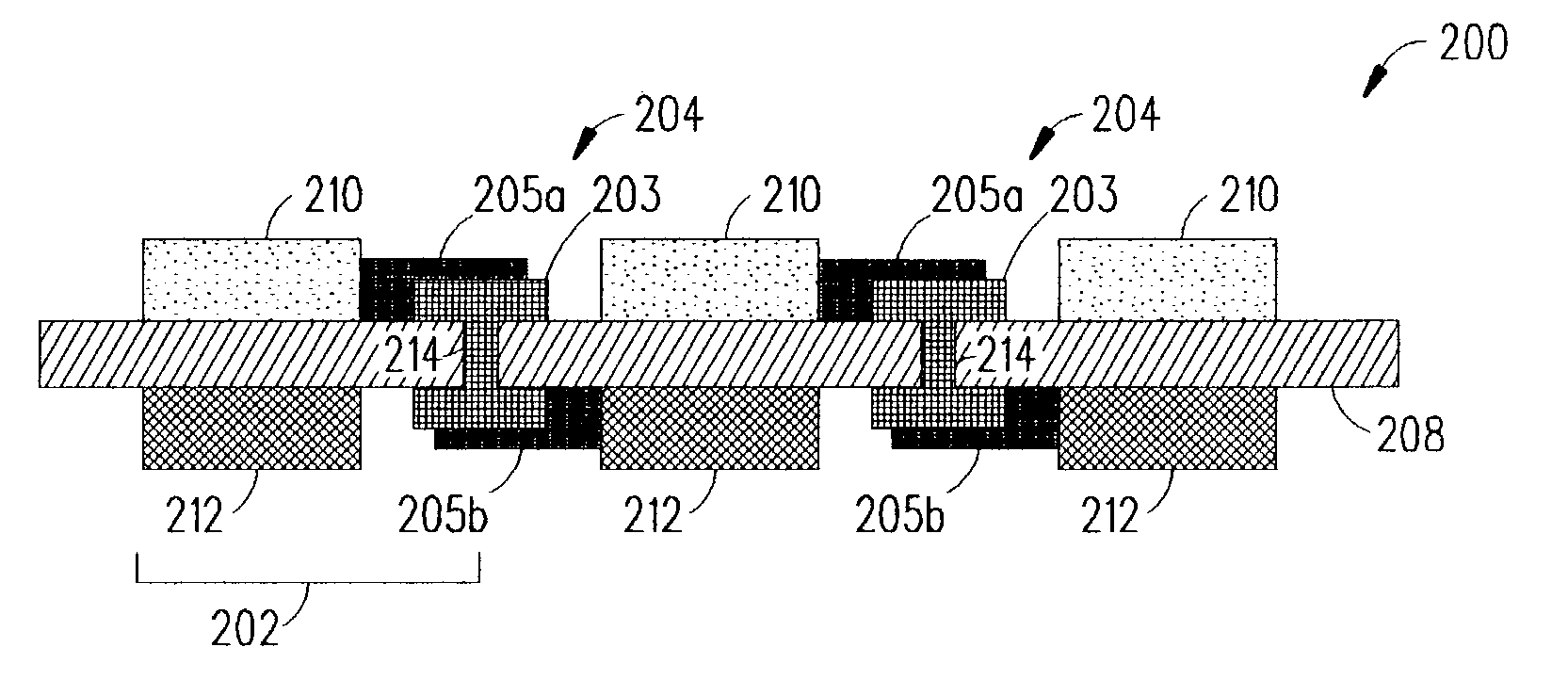
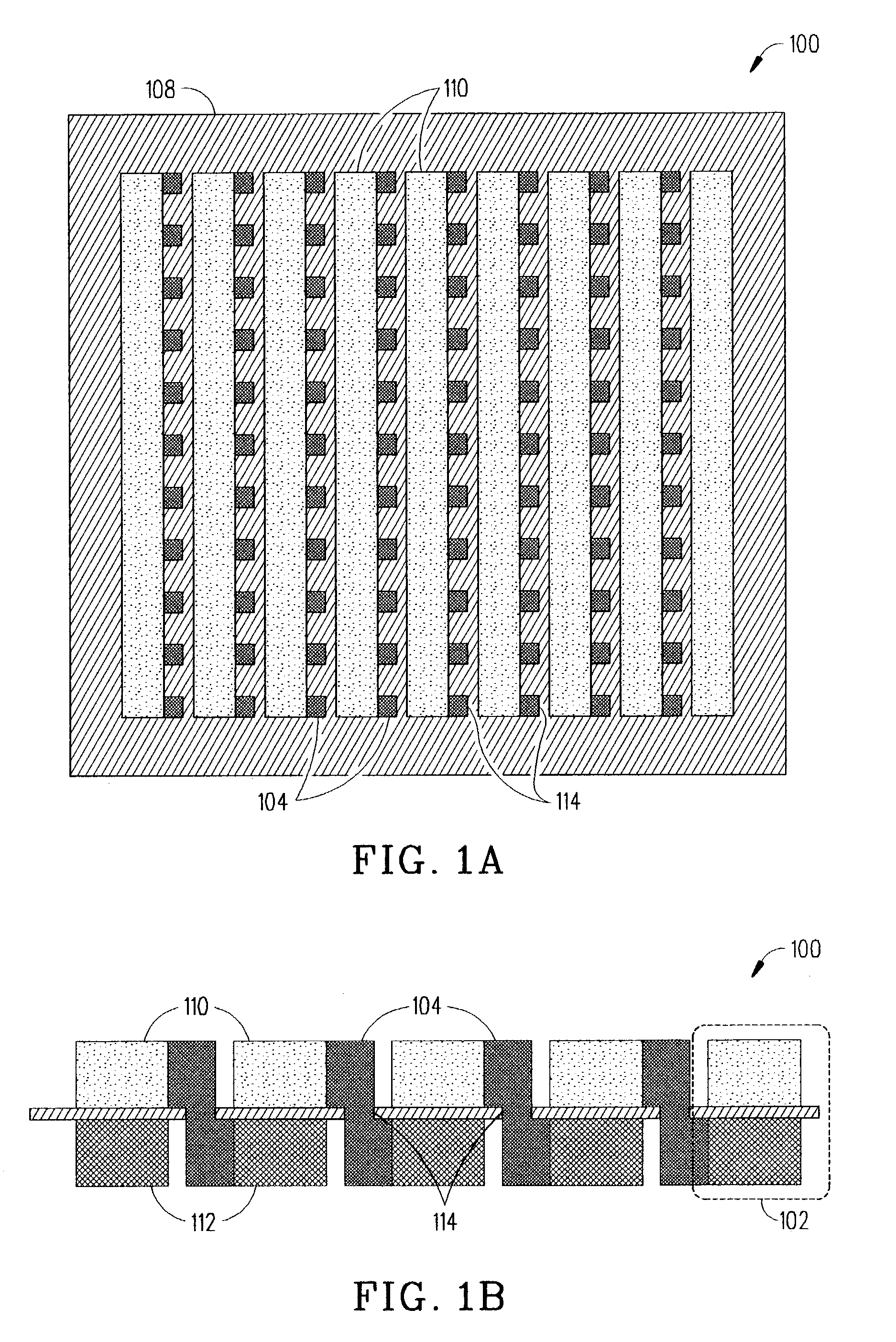
[0023] Via holes 114 were punched in an unsintered tape cast electrolyte sheet 108 of zirconia 3-mole % yttria. The electrolyte sheet 108 was sintered at 1430.degree. C. for 2 hours. The sintered electrolyte sheet 108 was about 20 microns thick and the via holes 114 were about 75 microns in diameter. Different composition ranges of LaCrO.sub.3 with silver-palladium-platinum, gold-platinum-palladium, silver-palladium-rhodium, gold-rhodium-palladium and mixes thereof were made into inks and painted or screen printed into the via holes 114 to form electrical conductors 104'. The electrical conductors 104' were sintered for up to 2 hours in a temperature range of 800-1430.degree. C. in air which was hot enough to form a gas tight seal and electrical continuity through the electrolyte sheet 108. The electrical conductors 104' made from cermets with up to 80% volume of LaCrO.sub.3 and metallic alloy did not crack the electrolyte sheet 108. Cermets with greater than 95% volume of LaCrO.sub...

example # 1

EXAMPLE #1

Second Embodiment

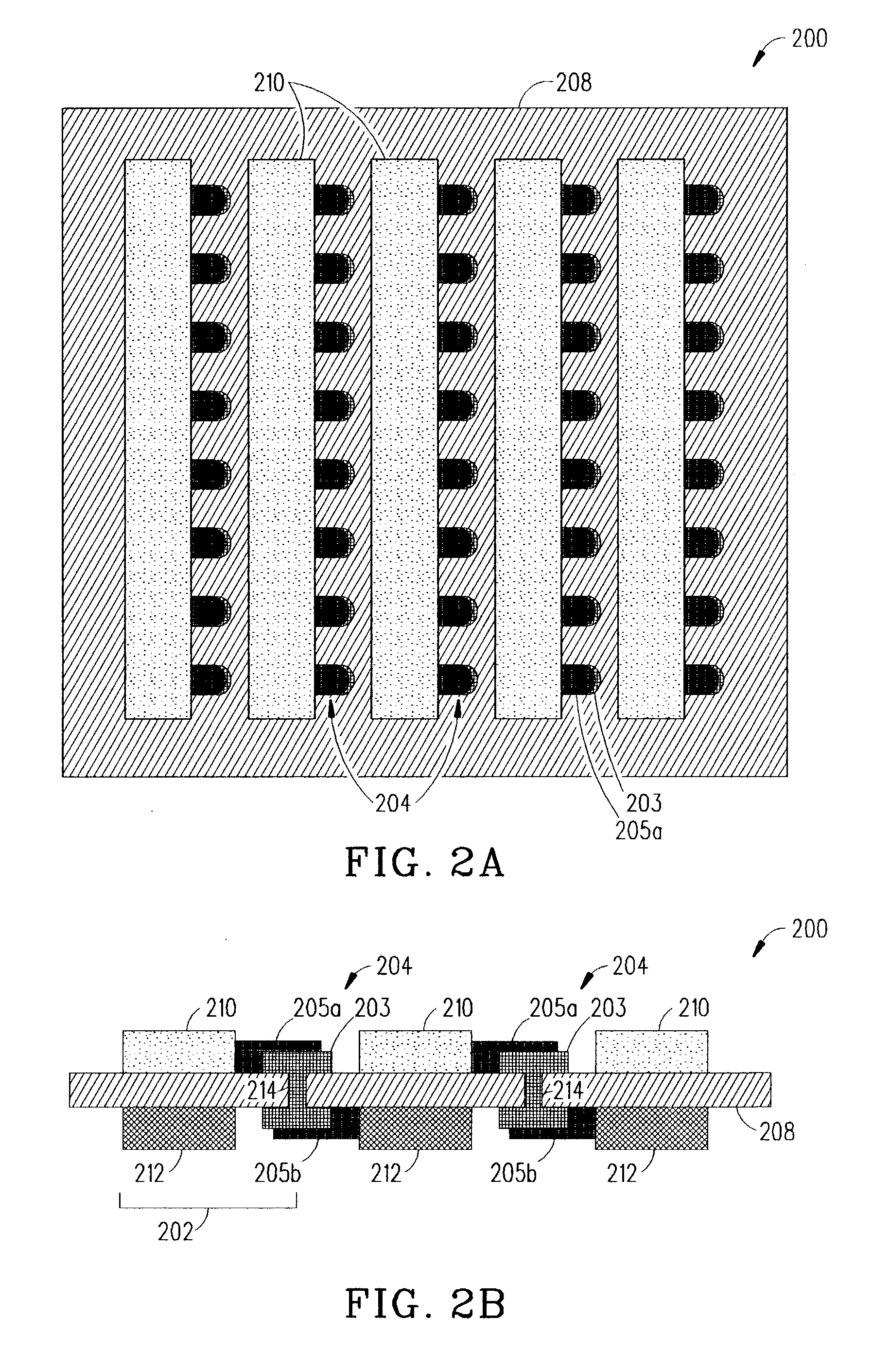
[0028] Via holes 114 were punched in an unsintered tape cast electrolyte sheet 108 of zirconia 3-mole % yttria. The electrolyte sheet 108 was sintered at 1430.degree. C. for 2 hours. The electrolyte sheet 108 was about 20 microns thick, and the via holes 114 were about 75 microns in diameter. A composition of 34% volume of gold, 50% volume of platinum and 16% volume of palladium was made into an ink and screen printed in the via holes 114 to form the electrical conductors 104". The electrical conductors 104" were sintered for up to 1 hour in a temperature range of 1350.degree. C. in air, resulting in a gas tight seal and electrical continuity through the electrolyte sheet 108.

example # 2

EXAMPLE #2

Second Embodiment

[0029] Via holes 114 were punched in an unsintered tape cast electrolyte sheet 108 of zirconia 3-mole % yttria. The electrolyte sheet 108 was sintered at 1430.degree. C. for 2 hours. The electrolyte sheet 108 was about 20 microns thick, and the via holes 114 were about 75 microns in diameter.

[0030] Via pad print: an ink containing silver and 10% palladium was screen printed in the form of a via contact pad, dried and fired at 900.degree. C. for 1 hour in air. A porous paper located underneath the via hole during printing was used to absorb any ink filling the hole--ensuring the via hole itself was not filled.

[0031] Via fill print: an ink containing 100% gold was screen printed over the fired 90% silver and 10% palladium via pads, in a pattern covering an area immediately about the via hole, dried and fired at 900.degree. C. for 1 hour in air. A non-wetting surface (wax paper) was located underneath the via hole to promote filling by the gold ink. This tech...


PUM


Abstract

A fuel cell and method for manufacturing the fuel cell are described herein. Basically, the fuel cell is formed from an electrode/electrolyte structure including an array of anode electrodes and cathode electrodes disposed on opposing sides of an electrolyte sheet, the anode and cathode electrodes being electrically connected in series, parallel, or a combination thereof by electrical conductors that traverse via holes in the electrolyte sheet. Several different embodiments of electrical conductors which have a specific composition and/or a specific geometry are described herein.

Description

CLAIMING BENEFIT OF PRIOR FILED APPLICATIONS[0001] This application is a Continuation-In-Part of U.S. patent application Ser. No. 09 / 858,124 filed on May 15, 2001, now pending, which claimed the benefit of U.S. provisional application Serial No. 60 / 205,273 filed on May 18, 2000 both of which are incorporated by reference herein.[0002] 1. Field of the Invention[0003] The present invention relates to fuel cells and, in particular, to a fuel cell formed from an electrode / electrolyte structure including at least one anode electrode and at least one cathode electrode disposed on opposing sides of an electrolyte sheet, the anode and cathode electrodes are electrically connected in series, parallel, or a combination thereof by at least one electrical conductor which has a specific composition and / or a specific geometry that traverses at least one via hole in the electrolyte sheet.[0004] 2. Description of Related Art[0005] The demand for electricity has increased dramatically in the past fe...

Claims


Application Information

Patent Timeline
IPC IPC(8): H01M4/86H01M8/02H01M8/12H01M8/24
CPCH01M4/8621H01M4/9066H01M8/0206H01M8/0208H01M8/0247Y02E60/525H01M8/1206H01M8/1226H01M8/1246H01M8/2425Y02E60/521H01M8/0256H01M8/1231Y02E60/50Y02P70/50H01M8/2428H01M8/2457H01M8/2432
Inventor BADDING, MICHAEL E.BROWN, JACQUELINE L.KETCHAM, THOMAS D.SCHIEFELBEIN, SUSAN L.JULIEN, DELL J. ST.WUSIRIKA, RAJA R.
Owner CORNING INC
Why Eureka
Try Eureka