
Single-piece seal assembly

Inactive Publication Date: 2004-02-19
ACD
View PDF0 Cites 0 Cited by
  • Summary
  • Abstract
  • Description
  • Claims
  • Application Information

AI Technical Summary

Benefits of technology

[0022] The invention is a single-piece seal assembly used to prevent escape of cryogenic materials in cryogenic pump applications. The single-piece seal assembly also is effective in keeping atmospheric contaminants out. The single-piece seal assembly reduces the installation time and reduces the chances of contamination and human error.
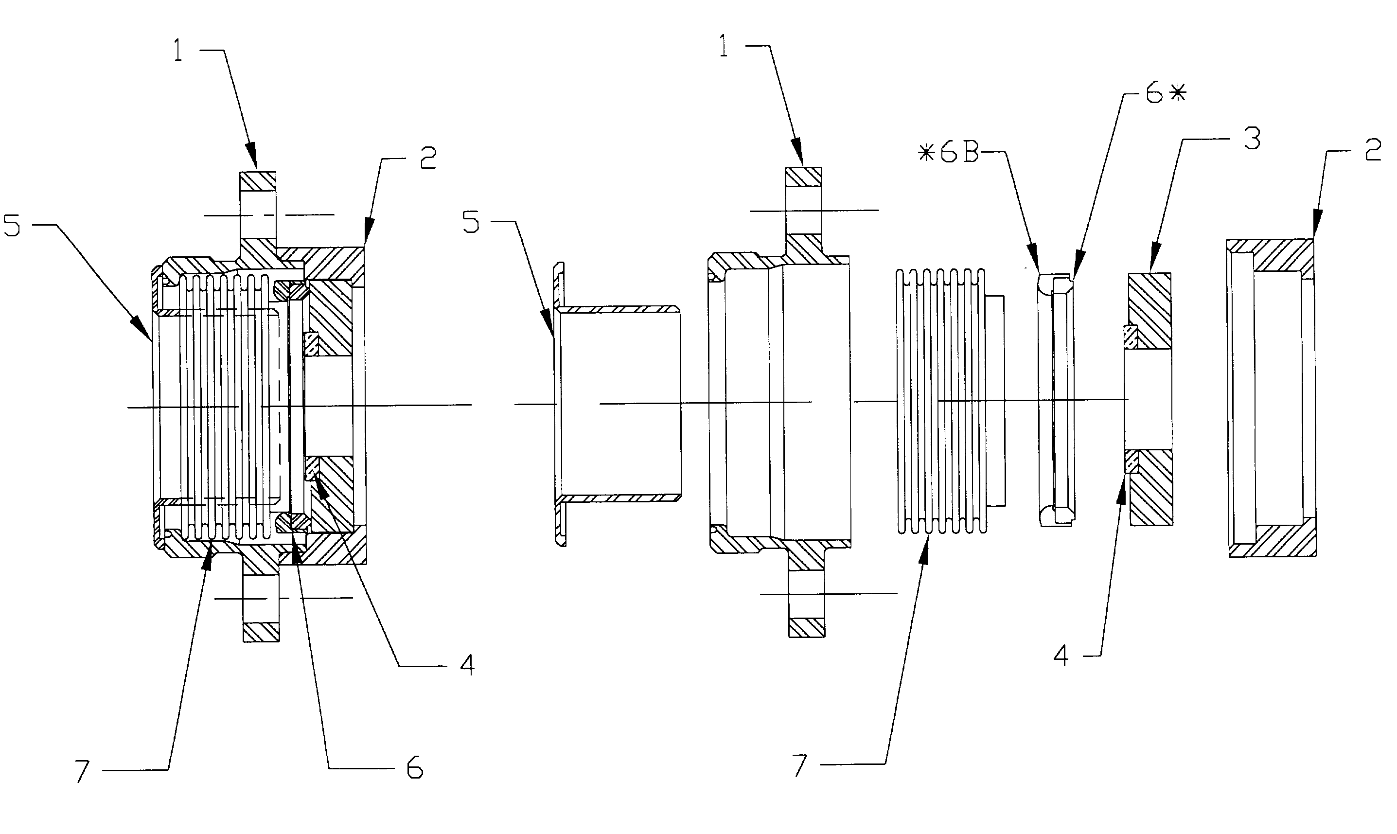
[0024] To manufacture the single-piece seal assembly (hereinafter referred to as "seal-assembly"), discrete sealing components are inserted into a seal body followed by a retainer which is fit onto the seal body to secure the components together, thereby forming the completed seal assembly. The bellows having a preset height provides the dimensional stability needed for the single-piece design. This bellows produces a stable and consistently accurate seal height, eliminating the need for a dial indicator measurement to determine the shim dimension for each installation, which as mentioned above, is currently the practice. The seal assembly includes a single shim stack equivalent ("shim"), which is adapted to provide a compressed state that will obtain a seal compression within the manufacturer's specified range. The shim is fitted into a machined notch in the rotating seal. The retainer secures all seal components within the seal body to create the single-piece seal assembly.

Problems solved by technology

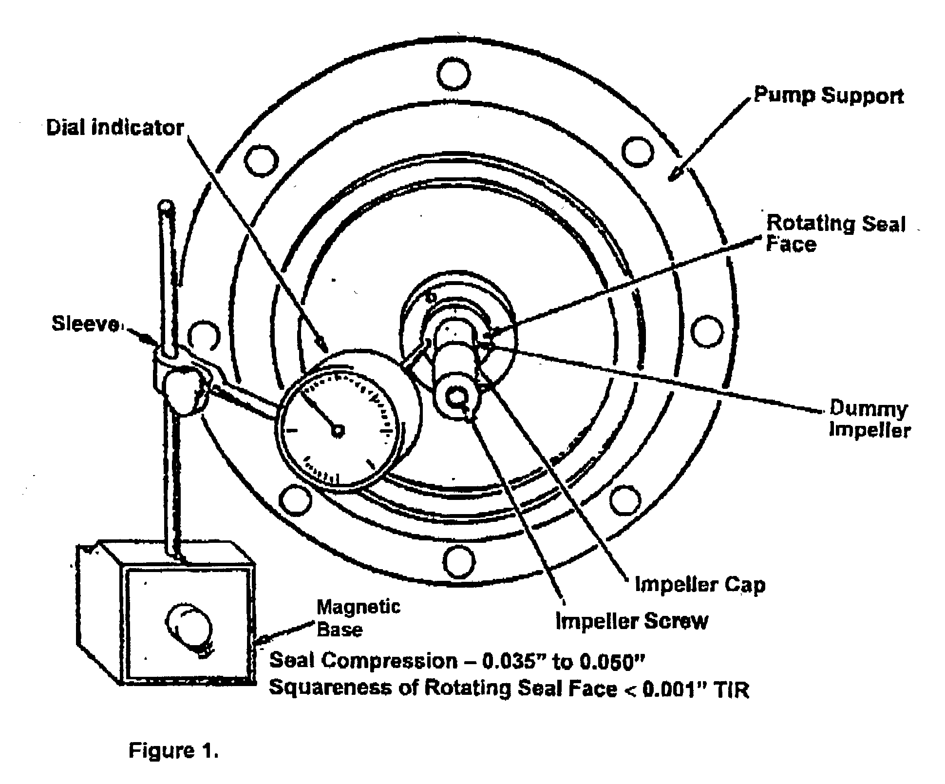
A seal assembly with a seal compression outside of the range will not operate properly.
If correct seal compression still cannot be obtained, a shaft extension may be required.
This standard practice for installing the multi-part seal presents the following disadvantages:
1. Dimensional variations occur resulting in a varying amount of shims necessary to achieve proper seal compression;
2. As a consequence of the dimensional variations, no means of retaining the components within the seal body has been developed. Therefore, up until now and under the current practice, a single-piece universal seal was not possible;
3. The current sealing practice makes the assembly of the shaft seal time-consuming due to the labor-intensive nature of taking careful height measurements and selection of the suitable shim stack;
4. The labor intensive nature of the current practice increase the probability that the seal components will become contaminated from handling; and
5. There is an increased risk of human error.

Method used


Image

  • Single-piece seal assembly
  • Single-piece seal assembly
  • Single-piece seal assembly

Examples


Embodiment Construction

[0029] Preferred materials for each component are listed, however, materials with similar qualities and characterizations which will not change the efficacy of the invention may be used. The invention is a single-piece cryogenic seal assembly, which includes all the required sealing components of multi-part seals, i.e., bellows, rotatable seal, ring seal, ring seal holder, and a shim stack equivalent. The present invention uses a bellows, preferably welded stainless steel, having a pre-set height. Unlike the prior art, the claimed invention comprises a retainer that, in addition to securing the rotatable seal, enables all the seal components to be contained within the seal body. The dimensional accuracy and stability of the bellows employed in the invention ensures the consistent height of the shim.

[0030] Unlike multi-part seals which require careful height measurements and shimming, the single-piece seal assembly may be installed without taking any measurements. Assembly time is re...


PUM


Abstract

The invention is a single-piece seal assembly comprising an annular seal body. A retainer is positioned at a first end of the seal body. A rotable seal is concentric with the retainer and has a notch positioned on an inner diameter of a first face of said rotable seal. In the notch is positioned a single shim. The shim is of a length such that it is capable of providing a selected seal compression. An annular bellows having first and second ends is affixed to an inner diameter of the seal body. On the first end of the bellows is a ring holder. The ring holder holds a ring seal.

Description

BACKGROUND OF INVENTION[0001] 1. Field of the Invention[0002] This invention relates generally to cryogenic pump applications. More specifically, the invention relates to a seal assembly for cryogenic pump applications.[0003] 2. Description of the Background Art[0004] In cryogenic applications, cryogenic materials are pumped from a source to the point of application. The nature of the materials used in cryogenic applications require specialized instrumentality. For example, the pumps that move the cryogenic product from its source to the point of application are highly specialized as are the seal assemblies involved in the delivery pathway. A seal assembly for cryogenic applications must keep atmospheric contaminants out of the cryogenic material, while keeping the cryogenic materials inside the source to application pathway. To meet the specialized needs of cryogenic sealing, standard bearing shaft seals must compensate for the extraordinary contraction of materials immersed in the...

Claims


Application Information

Patent Timeline
IPC IPC(8): F16J15/34F16J15/36
CPCF16J15/363F16J15/348
Inventor HENNINGSON, CARL J.
Owner ACD
Learn More