
Gasket for supporting and sealing a curved object

Inactive Publication Date: 2006-01-05
N A TAYLOR CO INC +1
View PDF7 Cites 0 Cited by
  • Summary
  • Abstract
  • Description
  • Claims
  • Application Information

AI Technical Summary

Benefits of technology

[0008] It would thus be desirable to provide a gasket to facilitate windshield mounting that benefits from the structural characteristics of a dense rubber gasket, but is also flexible so as to properly seal the windshield without needing the many fasteners required with the conventional dense rubber gasket. It would also be desirable to reduce installation time by eliminating the need to caulk pre-drilled holes prior to installation.
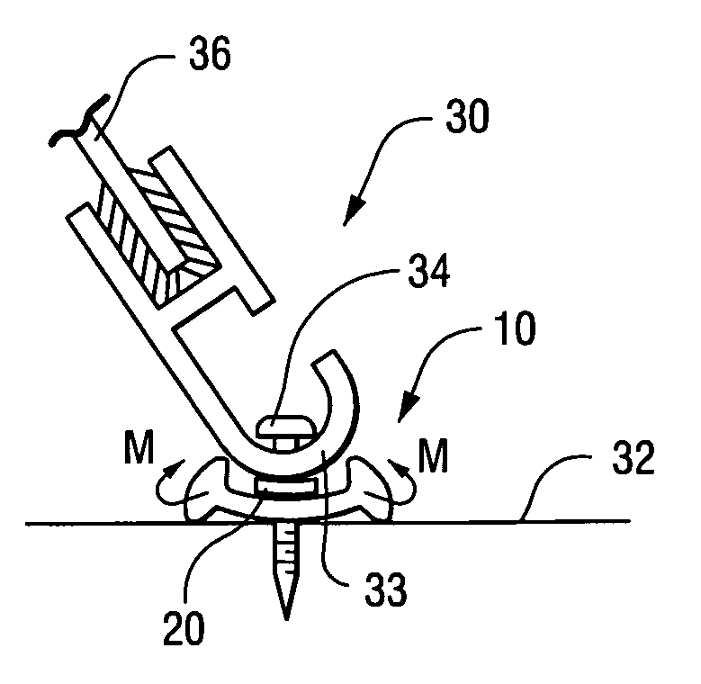
[0009] The gasket is designed with a receiving channel on an upper side thereof for receiving the bottom trim element or the like. A bottom of the gasket includes a deflection cavity that enables the support panel to deflect when the bottom trim element is set in the receiving channel and the assembly is fixed to a surface. When the gasket deflects by virtue of the bottom trim element being fixed to a surface, top portions of the receiving channel are deflected inwardly to thus provide a self-sealing assembly.

Problems solved by technology

Caulk, however, is messy and time-consuming to install.
The material also frequently gets distorted during the boat assembly process.
Moreover, final buffing of the product can smear the caulk and deteriorate the final product's appearance.
Sponge rubber gaskets may be faster to install, but the material does not hold up well to a finishing buffer, the environment or routine wear and tear.
Dense rubber provides a better appearance and stands up well to assembly finishing processes and the environment, but dense rubber material is not easily compressed and thus would not seal without very closely spaced windshield mounting fasteners.
This procedure of course adds time to the installation process.

Method used


Image

  • Gasket for supporting and sealing a curved object
  • Gasket for supporting and sealing a curved object

Examples


Embodiment Construction

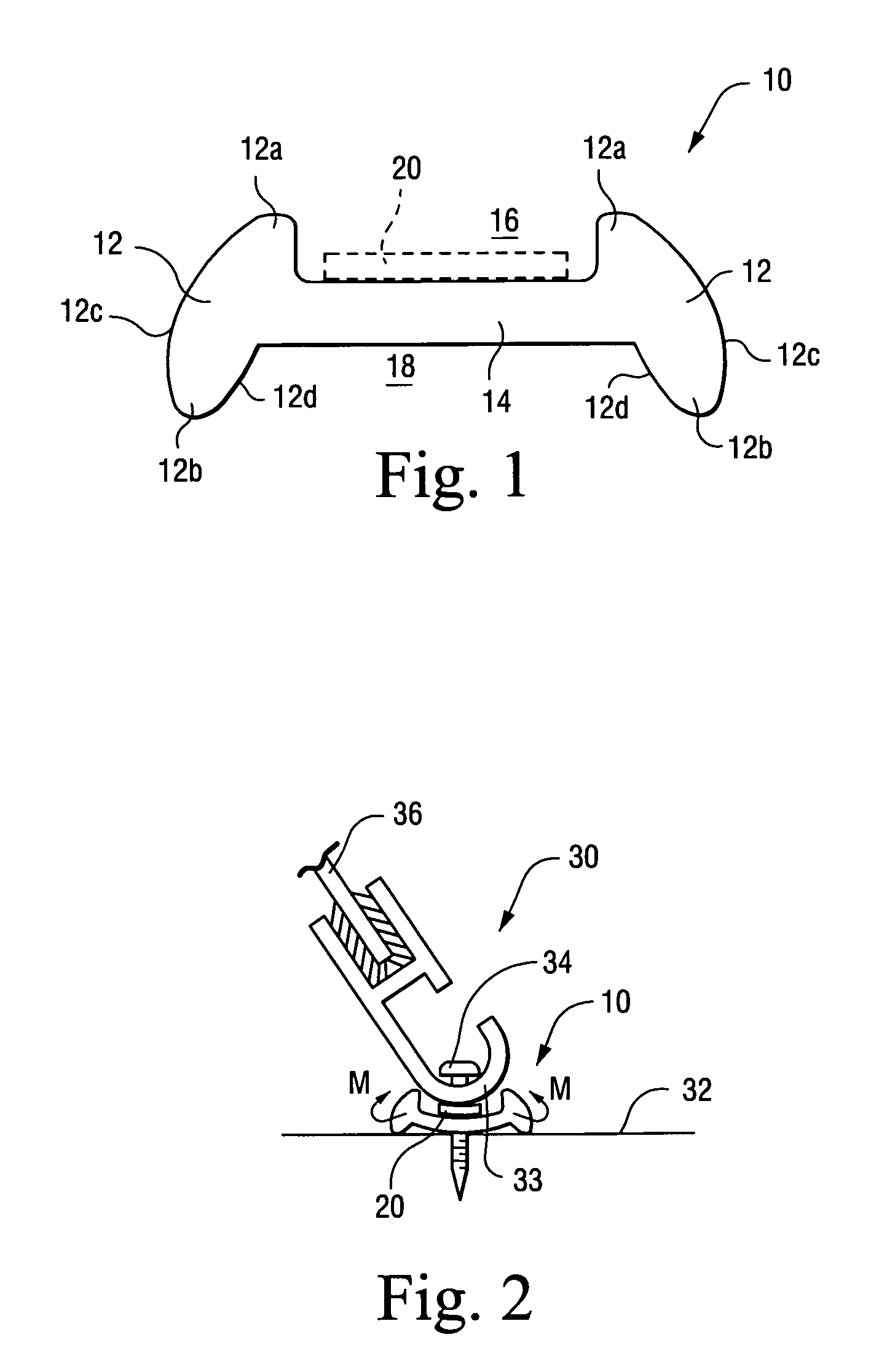
[0018] The gasket 10 of the present invention is shown in FIG. 1. The gasket 10 generally includes a pair of side rails 12 and a support panel 14 between the side rails 12. As shown, respective top portions 12a of the side rails 12 extend above the support panel 14 and define an object receiving channel 16 on an upper side of the gasket 10. Respective bottom portions 12b of the side rails 12 extend below the support panel 14 and define a deflection cavity 18 on a lower side of the gasket 10.

[0019] As shown, an exterior surface 12c of each of the side rails 12 is generally angled inwardly from the bottom portions 12b to the top portions 12a. An interior surface 12d of each of the side walls 12 in the deflection cavity 18 is angled inwardly from the bottom portions 12b to the support panel 14. As a consequence, the bottom portions 12b extend wider than the top portions 12a.

[0020] An adhesive, such as an adhesive tape 20, is preferably applied to the support panel 14 in the object re...


PUM


Abstract

A self-sealing gasket is suitable for sealing a curved object to a surface. The gasket includes a pair of side rails and a support panel between the side rails. Respective top portions of the side rails extend above the support panel to define an object receiving channel on an upper side of the gasket. Respective bottom portions of the side rails extend below the support panel to define a deflection cavity on a lower side of the gasket. The gasket is formed of a flexible material such that when the curved object is received in the object receiving channel and the curved object and gasket are fixed to the surface, the top portions of the side rails deflect inward to seal the curved object. By virtue of material deflection, a dense material may be used for the gasket while maintaining flexibility.

Description

CROSS-REFERENCES TO RELATED APPLICATIONS [0001] (Not Applicable) STATEMENT REGARDING FEDERALLY SPONSORED RESEARCH OR DEVELOPMENT [0002] (Not Applicable) BACKGROUND OF THE INVENTION [0003] It is desirable to fix a curved windshield to a boat hull in a boat assembly process to provide better aerodynamic performance and improve the appearance of the final product. In order to accommodate a curved windshield, the windshield mounting angle must be variable during installation, thus requiring a specially configured bottom trim element that can adequately support the windshield while being positionable at different angles for securement to the boat. [0004] Suitable bottom trim elements are described in U.S. Pat. No. 4,815,410 and U.S. Pat. No. 6,453,841, the contents of which are hereby incorporated by reference. These bottom trim elements generally include a curved bottom portion that can be secured to the boat hull at varying angles. In installation, it is important to properly seal the ...

Claims


Application Information

Patent Timeline
IPC IPC(8): B63B17/00B63B17/02
CPCB63B17/00
Inventor ERSKINE, EDWARD J.IRWIN, DAVID R.
Owner N A TAYLOR CO INC
Learn More