Installation tool for setting anchors

Active Publication Date: 2004-08-26
ASIA FASTENING US
View PDF18 Cites 7 Cited by
  • Summary
  • Abstract
  • Description
  • Claims
  • Application Information

AI Technical Summary

Benefits of technology

0011] A primary object of the invention is to provide an installation tool which utilizes the mechanical advantage of a threaded shaft incorporated in the tool and a power d

Problems solved by technology

These prior art methods have a number of disadvantages associated with them.
Second, the tools used for setting the anchors require a hammer strike to set the anchors.
Problems can occur if the material in which the anchor is to be set is fractal or brittle as the hammer strike can initiate a crack in the substrate that can compromi

Method used


Image

  • Installation tool for setting anchors
  • Installation tool for setting anchors
  • Installation tool for setting anchors

Examples


Example

[0031] Attention is now directed to the two embodiments of the setting tool 120, 320. A first embodiment of the setting tool 120 is shown in FIGS. 5-13. A second embodiment of the setting tool 320 is shown in FIGS. 14-18. Like elements are denoted with like reference numerals with the first embodiment being in the one and two hundreds, and the second embodiment being in the three and four hundreds.

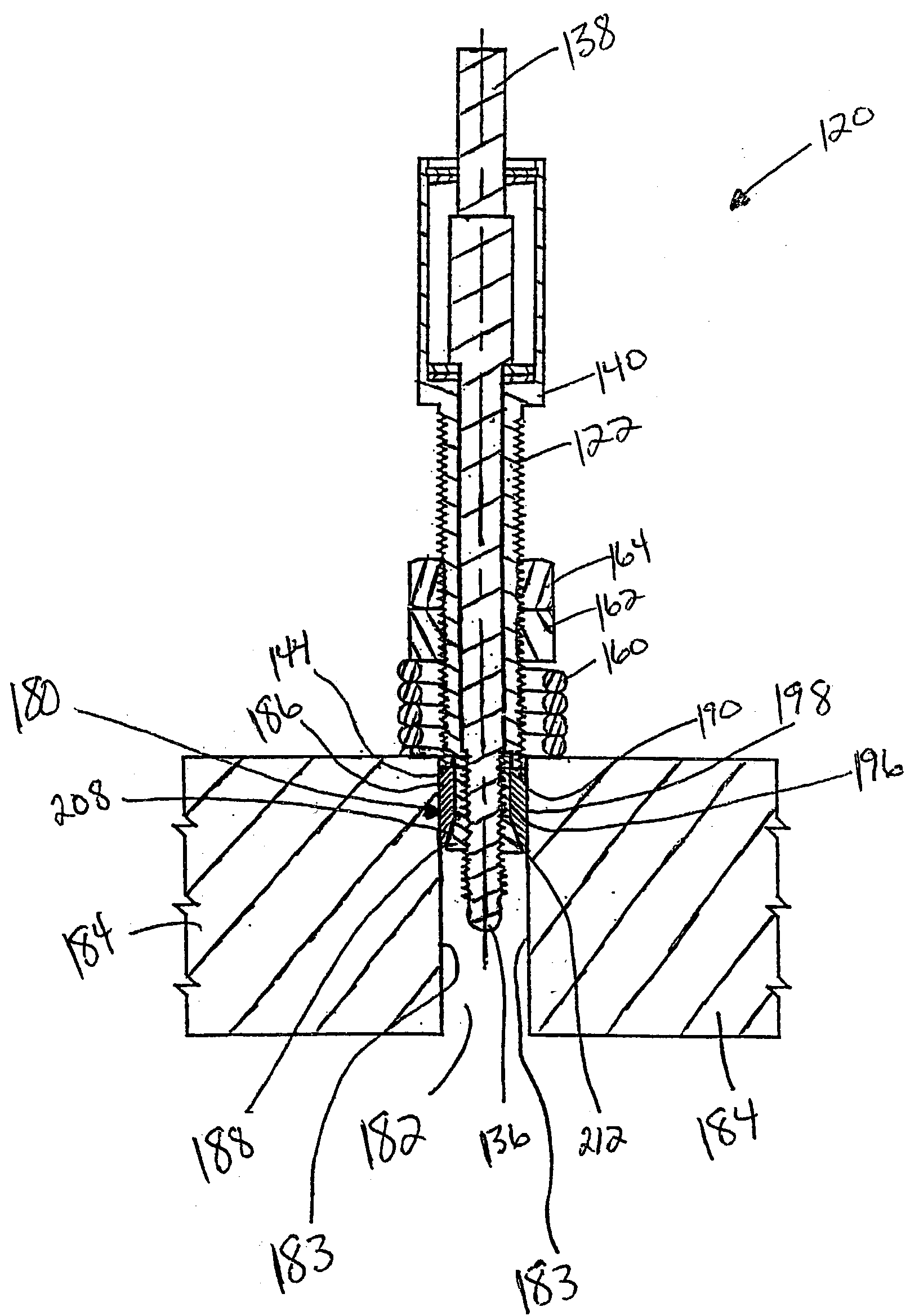
[0032] FIG. 7 illustrates a setting tool 120 of the first embodiment of the present invention. The setting tool 120 has a tool shaft 122. As best illustrated in FIG. 5, the tool shaft 122 has a first end 124 and a second end 126. At the first end 124 of the tool shaft 122, the tool shaft 122 has a first portion 128 which has a diameter D1. Extending from the first portion 128, the tool shaft 122 has a second portion 130 which has a diameter D2, with diameter D1 being larger than diameter D2, such that a shoulder 132 is defined between the first and second portions 128, 130 of the tool shaf...

Example

[0059] Attention is now directed to the second embodiment of the setting tool 320 which is illustrated in FIGS. 14-18. The setting tool 320 has a tool shaft 322. As best illustrated in FIG. 14, the tool shaft 322 has a first end 324 and a second end 326. At the first end 324 of the tool shaft 322, the tool shaft 322 has a first portion 328 which has a diameter D1. Extending from the first portion 328, the tool shaft 322 has a second portion 330 which has a diameter D2, with diameter D1 being larger than diameter D2, such that a shoulder 332 is defined between the first and second portions 328, 330 of the tool shaft 322. Extending from the second portion 330, the tool shaft 322 has a third portion 334 which is externally threaded and which has a diameter which is substantially commensurate with the diameter D2 of the second portion 330 of the tool shaft 322. Extending from the third portion 334, the tool shaft 322 has a tip portion 336, which extends to the second end 326 of the tool...


PUM

PropertyMeasurementUnit
Lengthaaaaaaaaaa
Pressureaaaaaaaaaa
Diameteraaaaaaaaaa

Abstract

The invention provides an installation tool for use with a battery operated drill or a corded electric drill for repetitive installation of caulk-in anchors. The installation tool utilizes the mechanical advantage of a threaded shaft to improve consistency of the holding reliability of the caulk-in anchor and controls the anchor setting process to insure proper installation while reducing installation time. The installation tool does not rely on bottom setting or a hammer strike to set the anchor, but can be set at a depth independent of hole depth. In one embodiment, the tool can be used with a through hole in the substrate and uses a combination of a threaded shaft and a controlled sensing spring to insure a more uniform installation of the anchor within the substrate across the entire length of the sleeve portion of the anchor, along with a visual check of proper setting of the anchor.

Description

[0001] The present invention relates to a tool used for the installation of caulk-in anchors.[0002] Two prior art examples of tools used for the installation of caulk-in anchors are illustrated in FIGS. 1-4. A first prior art tool 20 is illustrated in FIGS. 1 and 2 for setting an anchor 22 within a hole 24 of a substrate 26. The anchor 22 has a hollow cone portion 28 which is positioned within a hollow sleeve portion 30. The cone portion 28 has an enlarged head portion 32 at one end thereof which is not positioned within the hollow sleeve portion 30. The anchor 22 is of a bottom-setting type such that the enlarged head portion 32 of the cone portion 28 of the anchor 22 is positioned against the base 34 of the hole 24 of the substrate 26 to prevent movement of the cone portion 28 of the anchor 22 upon setting of the anchor 22 within the hole 24.[0003] The tool 20 has an enlarged diameter portion 36, which is slightly smaller than a diameter of the hole 24 of the substrate 26, and a s...

Claims


Application Information

Patent Timeline
IPC IPC(8): B25B31/00
CPCB25B31/00Y10T29/4994Y10T29/53909Y10T29/49881Y10T29/53848Y10T29/49938
Inventor JANUSZ, MICHAEL
Owner ASIA FASTENING US
Why Eureka
Try Eureka