Building method and structure

Inactive Publication Date: 2004-03-04
BURNESS ROBERT GEOFFREY
View PDF43 Cites 9 Cited by
  • Summary
  • Abstract
  • Description
  • Claims
  • Application Information

AI Technical Summary

Problems solved by technology

However, in many cases, such panel structures perform load-bearing functions and this places limitations on their design

Method used


Image

  • Building method and structure
  • Building method and structure
  • Building method and structure

Examples


Embodiment Construction

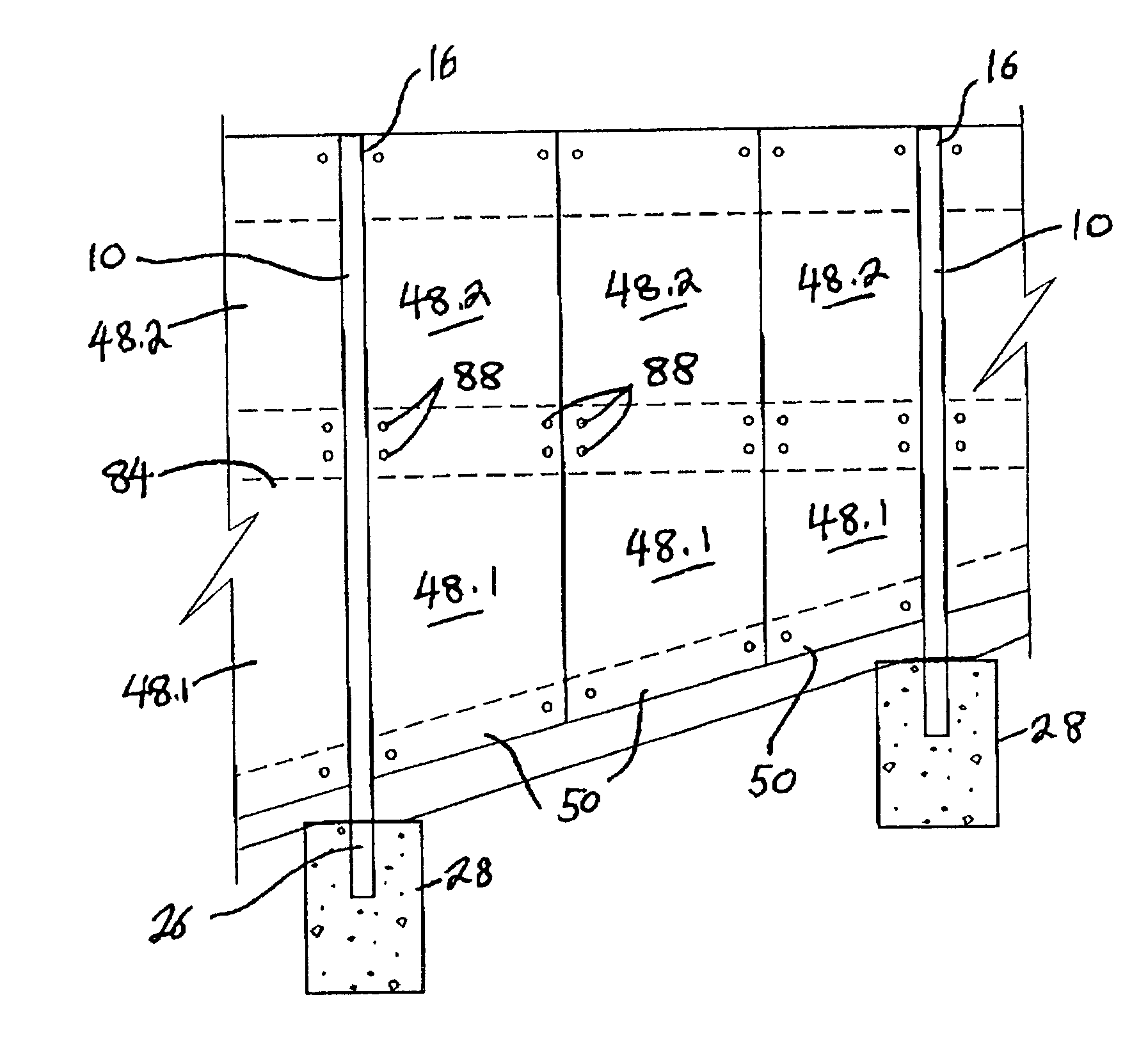
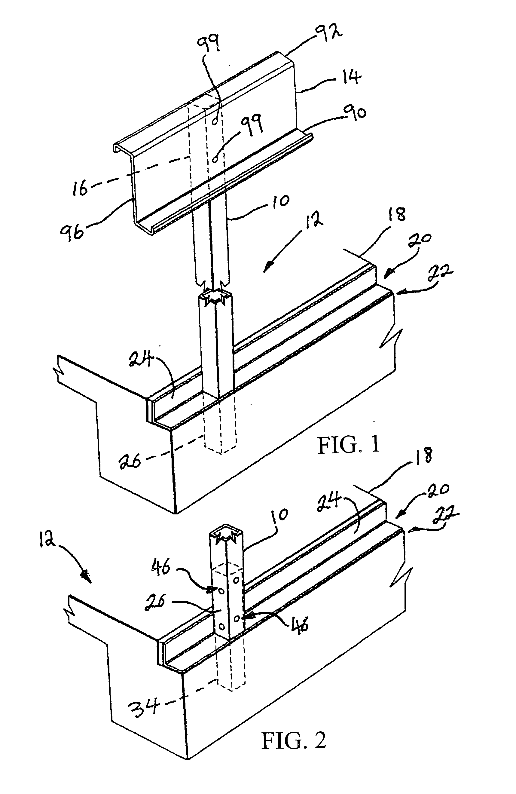
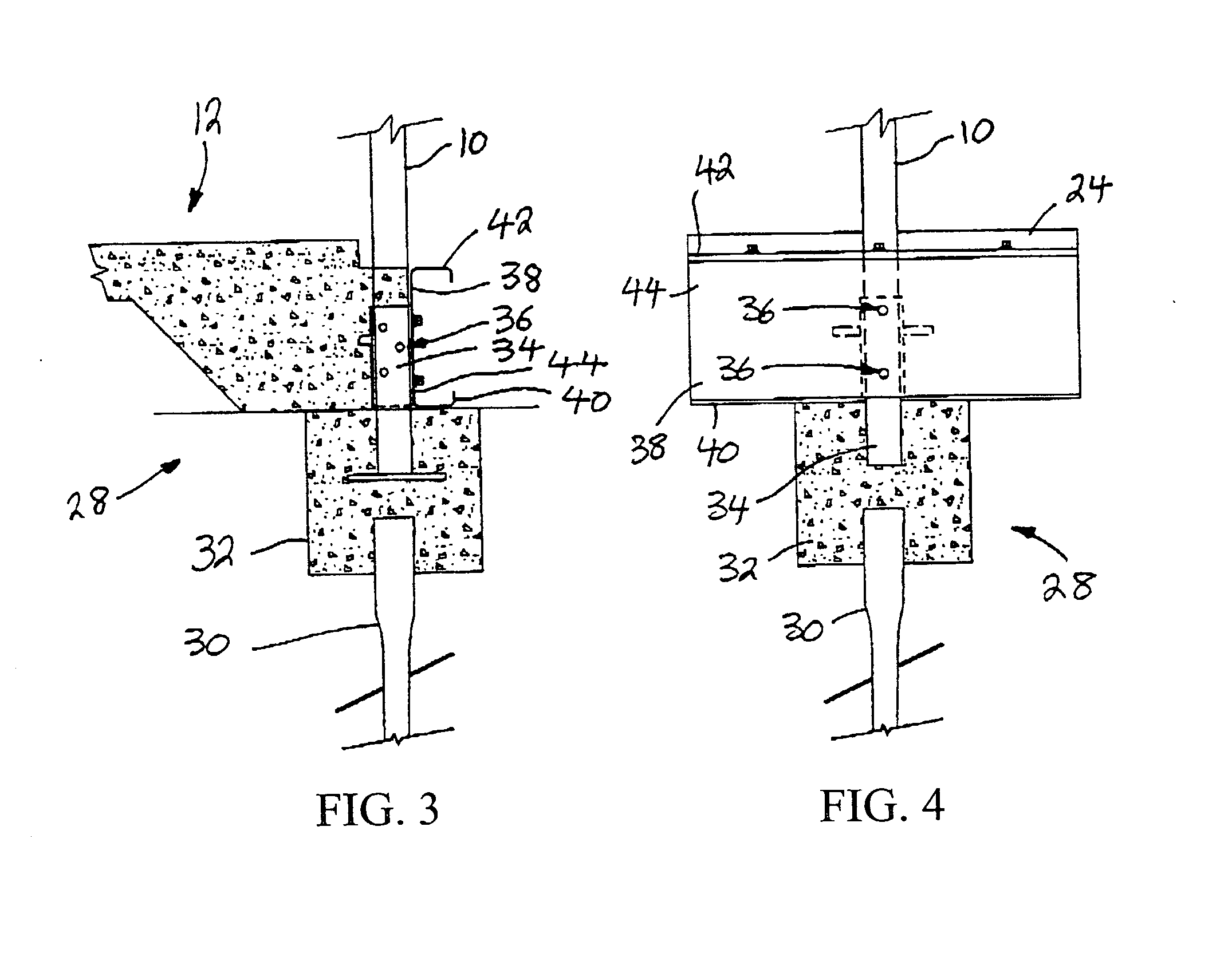
[0041] A structure, in accordance with a preferred embodiment of the invention and built according to a preferred method of the invention includes a number of support posts 10.

[0042] Each support post 10 is of steel. It is to be appreciated that the applicant envisages that the support post may be of any suitably strong material, such as aluminium or, possibly, some other high strength composite. In this particular example, each support post 10 has a substantially rectangular cross section. However, it is to be appreciated that each support post 10 can have a number of different cross sections, some of which are indicated in FIG. 15.

[0043] In use, the support posts 10 are mounted on a substrate in a spaced apart, substantially upright orientation so that the support posts 10 bound a floor area 12. In the embodiment the support posts are vertical.

[0044] An upper support means in the form of a number of roof support beams 14 are mounted on upper portions 16 of the support posts 10. In...


PUM


Abstract

A method of building a structure includes the step of mounting a number of support posts on a substrate in a spaced apart, substantially upright orientation, so that at least one floor area is bounded by the support posts. An upper support means is mounted on operatively upper end portions of the support posts. At least one panel is positioned between consecutive support posts. The panels are fixed in position between the support posts. The method includes the step of arranging the support posts and the upper support means so that substantially all load bearing functions are performed by the support posts and upper support means. A structure erected in accordance with said method is also claimed.

Description

BACKGROUND OF THE DESCRIPTION[0001] 1. Field of the Invention[0002] This invention relates to building. More particularly, this invention relates to a method of building a structure and to a structure erected by the method.[0003] 1. Discussion of the Background Art[0004] Many conventional building techniques require the use of panel structures. However, in many cases, such panel structures perform load-bearing functions and this places limitations on their design. An example of such a limitation is the necessity for cladding which serves to seal the panels and to provide insulation.[0005] The applicant has found that it is possible to provide a means whereby suitable panels can be used in such a way that cladding is unnecessary. The applicant has found that this can be achieved by providing suitable building components, apart from the panels, to perform load-bearing functions. This allows the panels to be provided in a suitable configuration to perform their conventional role and th...

Claims


Application Information

Patent Timeline
IPC IPC(8): E04B1/24E04C3/02E04C3/32E04D3/40
CPCE04B1/24E04B2001/2454E04B2001/2463E04B2001/2466E04D3/40E04B2001/2484E04C3/02E04C3/32E04C2003/023E04B2001/2481
Inventor BURNESS, ROBERT GEOFFREY
Owner BURNESS ROBERT GEOFFREY
Why Eureka
Try Eureka