Remote management system

Inactive Publication Date: 2004-03-11
YAMATAKE HONEYWELL CO LTD
View PDF7 Cites 1 Cited by
  • Summary
  • Abstract
  • Description
  • Claims
  • Application Information

AI Technical Summary

Benefits of technology

0006] The present invention has been made to overcome the conventional drawbacks, and has as its object to provide a

Problems solved by technology

It is determined that these air-conditioners may also fail be

Method used


Image

  • Remote management system
  • Remote management system
  • Remote management system

Examples


Example

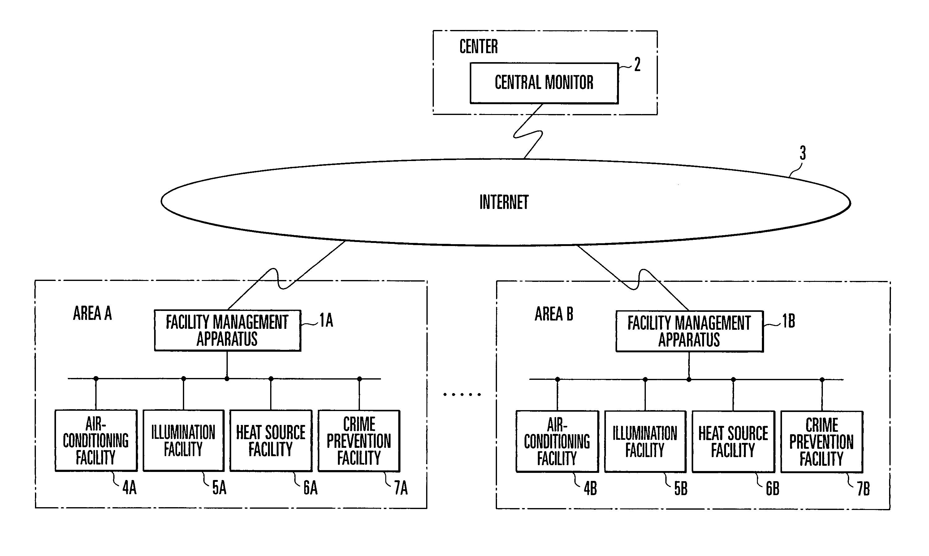
[0013] The present invention will be described in detail below on the basis of an embodiment. FIG. 2 is a view showing the system configuration of a remote management system according to the embodiment of the present invention. In FIG. 2, reference numeral 1A denotes a facility management apparatus in area A; 1B, a facility management apparatus in area B; 2, a central monitor at the center; and 3, a communication line (Internet).

[0014] The facility management apparatuses 1A and 1B and the central monitor 2 are connected via the Internet 3. The facility management apparatus 1A monitors the states of various facilities such as an air-conditioning facility 4A, illumination facility 5A, heat source facility 6A, and crime prevention facility 7A in area A, and performs operations such as the start / stop of operations of these facilities.

[0015] The facility management apparatus 1B monitors the states of various facilities such as an air-conditioning facility 4B, illumination facility 5B, he...


PUM


Abstract

A facility management apparatus (1A (1B)) generates element models for various components of a facility based on environmental data, measurement data, data inherent to the facility, and facility character information, defines a set of element models as a facility model, generates facility models for various facilities, and stores the facility models in a storage section (1A3 (1B3)). A central monitor (2) picks up the facility models of various facilities periodically from the facility management apparatus (1A (1B)), extracts similar element models from these facility models, and stores a set of extracted element models as a similar model group in a storage section (24). When a component is designated upon occurrence of some event, the central monitor (2) finds out a similar element model group including the element model of the designated component from the storage section (24).

Description

[0001] The present invention relates to a remote management system which manages the states of various facilities at geographically distant places via a communication line such as the Internet.[0002] In a conventional remote management system of this type, a facility management apparatus is installed in each area (e.g., a building), and the states of various facilities within the area are managed. Such facility management apparatuses are connected to the central monitor of the center via a communication line such as the Internet, and information is exchanged between the facility management apparatuses and the central monitor.[0003] More specifically, facility management apparatuses monitor various facility states such as air-conditioning, illumination, heat source, and crime prevention in areas A and B, and execute operations such as the start / stop of operations of these facilities. The central monitor accumulates pieces of information from the facility management apparatuses in are...

Claims


Application Information

Patent Timeline
IPC IPC(8): G05B17/02G05B23/02G06Q50/00G06Q50/10
CPCG05B23/0289G05B17/02
Inventor WATANABLE, TSUTOMU
Owner YAMATAKE HONEYWELL CO LTD
Why Eureka
Try Eureka