Gait generating system for mobile robot

Active Publication Date: 2007-07-19
HONDA MOTOR CO LTD
View PDF9 Cites 15 Cited by
  • Summary
  • Abstract
  • Description
  • Claims
  • Application Information

AI Technical Summary

Benefits of technology

[0063] In the aforesaid seventeenth invention, when determining each of the aforesaid m-th gait parameters, the (m−1)th gait parameter and the m-th dynamic model are used to generate a gait in the aforesaid predetermined period, at least one set of auxiliary gait parameters obtained by correcting, by a predetermined amount, the aforesaid parameter to be corrected out of the aforesaid (m−1)th gait parameters is determined, and the determined auxiliary gait parameters of each set and the aforesaid m-th dynamic model are used to generate a gait in the aforesaid predetermined period; therefore, when a parameter to be corrected out of the (m−1)th gait parameters is corrected, how a gait generated on the m-th dynamic model is changed can be observed, so that the correction amount of a parameter to be corrected out of the m-th gait parameters that satisfies a boundary condition on the m-th dynamic m

Problems solved by technology

However, a dynamic model with high linearity generally tends to have relatively low dynamic accuracy in a variety of operations of a robot.
More specifically, the kinetics of a robot on its dynamic model is prone to errors relative to the actual kinetics of an actual robot.
For this reason, if an instantaneous desired gait created using the first dynamic model is directly applied to the actual robot to make the actual robot operate, then a dynamic balance condition guaranteed on the first dynamic model will not be satisfied, frequently causing the operations of the actual robot to lack in stability.
And, in this case, the correction amount of the desired ZMP trajectory or the floor reaction force moment about the desired ZMP occasionally becomes relatively large, and in such a case, it has become difficult to maintain an ample stability margin.
Conversely, if the correction amount of the desired ZMP trajectory or

Method used


Image

  • Gait generating system for mobile robot
  • Gait generating system for mobile robot
  • Gait generating system for mobile robot

Examples


Example

[0120] A first embodiment in accordance with the present invention will now be specifically explained. According to the first embodiment, for each control processing cycle of the aforesaid control unit 60, the gait parameter determiner 100a uses a plurality of dynamic models to determine step by step a parameter for correcting a desired ZMP trajectory (more precisely, the parameter that defines a desired ZMP trajectory in a gait parameter) or exploratorily determine parameters other than the aforesaid parameter so as to determine a set of gait parameters that defines a desired gait. Then, the determined gait parameter and one dynamic model are used to determine the time series of the instantaneous values of a desired gait by the desired instantaneous value generator 100b.

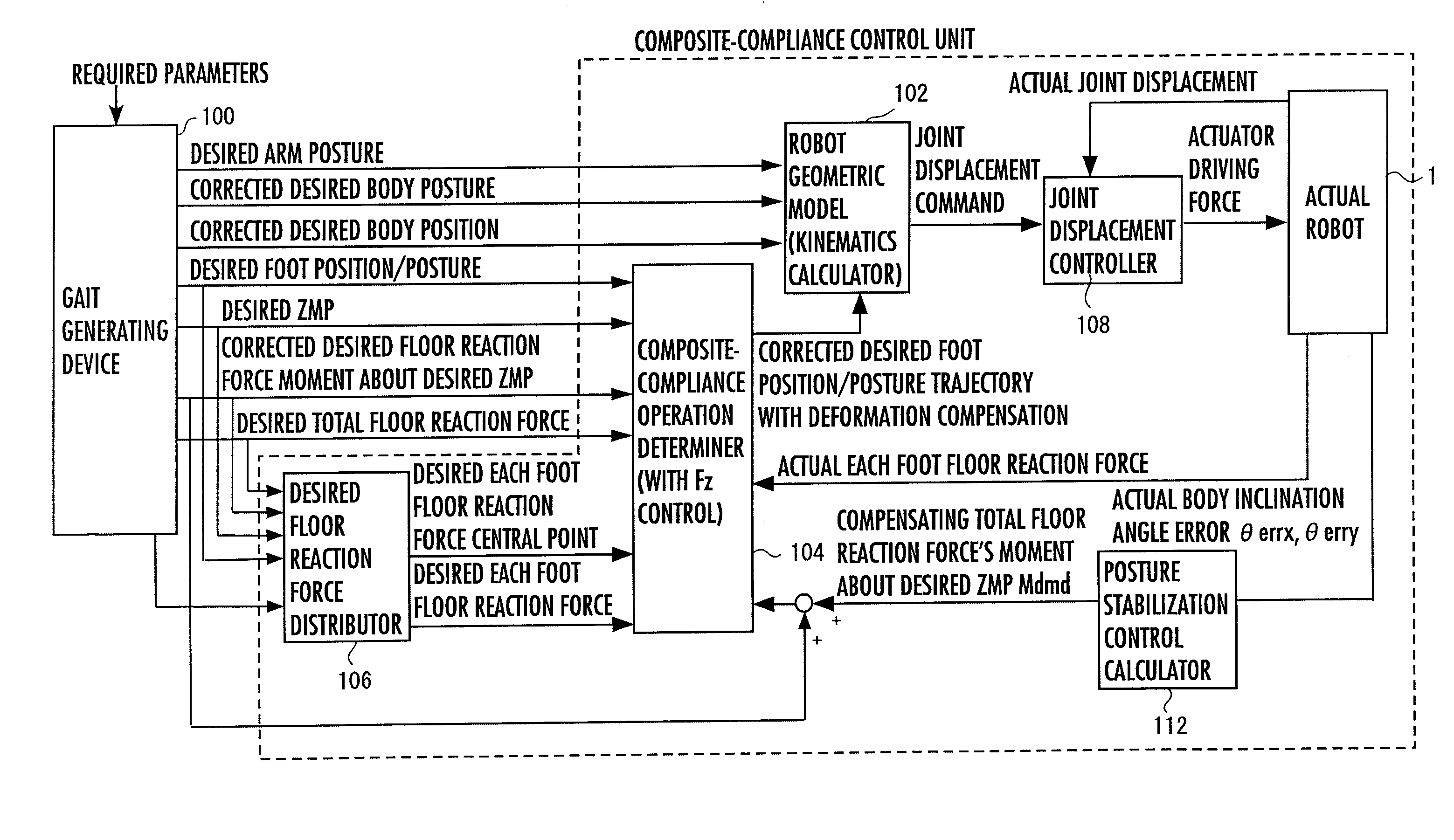
[0121] A body motion mode and dynamic models used for generating gaits in the first embodiment will now be explained.

[0122] In a gait that includes a floating period, such as a running gait, or walking on a low-fr...

Example

[0255] The above is the second embodiment according to the present invention.

[0256] According to the aforesaid first embodiment, in a plurality of dynamic models, the motion / floor reaction force models representing the relationships between their motions and floor reaction forces have been set to have structures that are different from each other. Alternatively, however, a plurality of dynamic models may share the same motion / floor reaction force models (the structures of the mass points, inertias, and the like and dynamic equations (equations of motion) of the models) and have different restrictive conditions related to motions or floor reaction forces of the robot 1 that are added to the individual dynamic models. The following will explain an example thereof as a third embodiment. The motion / floor reaction force models of the plurality of (three in the present embodiment) of dynamic models are set to be the same as the motion / floor reaction force models of, for example, the seco...

Example

[0257] Supplementally, according to the third embodiment, in the n-th dynamic model (n=1,2 or 3), the permissible range of a floor reaction force horizontal component broadens and the linearity increases as the value of n decreases. Hence, when searching for search objects of a gait parameter (a normal gait parameter or a current time's gait parameter) by the first dynamic model, the search processing can be promptly completed.

[0258] Further, the model having the highest dynamic accuracy among the plurality of dynamic models may be the same as the aforesaid full model. In this case, it is desirable to set the floor reaction force horizontal component permissible ranges for these plurality of dynamic models (the dynamic models used in S024 and S028 of FIG. 12 described above) to be wider than those for full-model correction in order to enhance the convergence of the search processing of a gait parameter.

[0259] Supplementally, it is effective for the plurality of dynamic models used...


PUM


Abstract

A gait generating system for a mobile robot has n dynamic models and determines a first gait parameter defining a desired gait such that the boundary condition of a gait on a first dynamic model is satisfied. The first gait parameter is corrected step by step by using an m-th dynamic model (m: integer satisfying 2≦m≦n), which is each dynamic model other than the first dynamic model, and an m-th gait parameter that satisfies the boundary condition on the m-th dynamic model is determined. The m-th gait parameter is determined by correcting an object of an (m−1)th gait parameter to be corrected on the basis of the degree of deviation of the gait generated on the m-th dynamic model by using the (m−1)th gait parameter from the boundary condition. A final determined n-th gait parameter and an n-th dynamic model are used to generate a desired gait.

Description

TECHNICAL FIELD [0001] The present invention relates to a system for generating gaits of a mobile robot, such as a bipedal mobile robot. BACKGROUND ART [0002] As techniques for generating desired gaits of a mobile robot, such as a bipedal mobile robot, one disclosed in, for example, Japanese Unexamined Patent Application Publication No. 2002-326173 (patent document 1) and one disclosed in PCT international publication WO / 03 / 057427 / A1(patent document 2) have been proposed by the present applicant. According to the techniques disclosed in these documents, an instantaneous desired gait composed of an instantaneous value of a desired motion (instantaneous desired motion) of a robot and an instantaneous value of a desired floor reaction force (instantaneous desired floor reaction force) is sequentially created using a first dynamic model (simplified model) representing a relationship between a motion of the robot (position and posture of each part) and a floor reaction force such that a ...

Claims


Application Information

Patent Timeline
IPC IPC(8): G06F19/00B25J5/00B25J13/00B62D57/032
CPCB62D57/032B25J5/00B25J13/00
Inventor TAKENAKA, TORUMATSUMOTO, TAKASHIYOSHIIKE, TAKAHIDE
Owner HONDA MOTOR CO LTD
Why Eureka
Try Eureka