Vehicle air conditioner

US20040050944A1Inactive Publication Date: 2004-03-18DENSO CORP

Image

  • Vehicle air conditioner
  • Vehicle air conditioner
  • Vehicle air conditioner

Examples


Embodiment Construction

[0028] Preferred embodiments of the present invention will be described hereinafter with reference to the appended drawings.

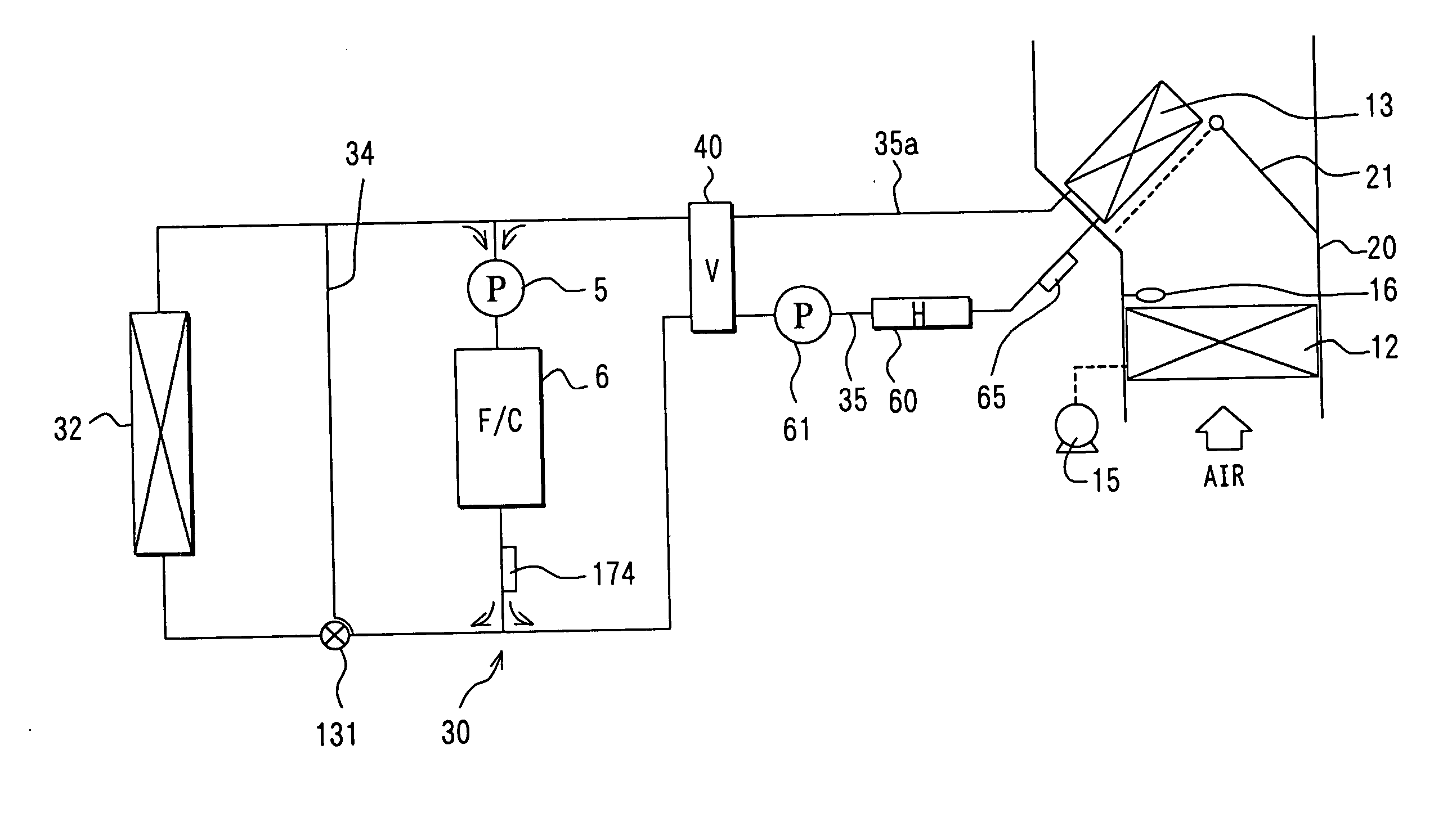
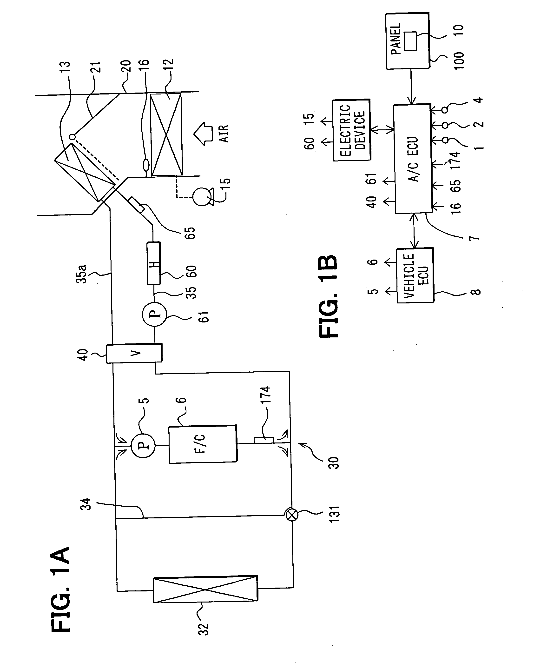
[0029] In a preferred embodiment, the present invention is typically applied to an air conditioner for a fuel cell vehicle, as shown in FIG. 1A. A fuel cell system (F / C) 6 is required to be temperature-controlled, and is connected to a cooling water circuit 30 where cooling water is circulated. The cooling water circuit 30 includes a first cooling-water passage 34 at a left side of the fuel cell system 6 in FIG. 1A and a second cooling-water passage 35 at a right side of the fuel cell system 6 in FIG. 1A. In the second cooling-water passage 35, cooling water is circulated between a heater core 13 and the fuel cell system 6. A water pump 5 is provided in the fuel cell system 6 to circulate cooling water in the cooling water circuit 30. The fuel cell system 6 is temperature-controlled with the cooling water in a temperature area (e.g., 72-80.degree. C.) where the...


PUM


Abstract

In an air conditioner for a vehicle having a temperature-controlled apparatus such as a fuel cell system, a heater core heats air by using unnecessary thermal energy from the fuel cell system. Further, a switching valve is controlled to switch between a first circuit and a second circuit. Cooling water is circulated between the heater core and the fuel cell system in the first circuit, and passes through the heater core while by passing the fuel cell system in the second circuit. When a cooling water temperature flowing from the heater core is lower than a cooling water temperature from the fuel cell system, the switching valve is controlled by a control unit to select the first circuit. Accordingly, the heater core can effectively use the unnecessary thermal energy from the fuel cell system.

Description

[0001] This application is related to and claims priority from Japanese Patent Application No. 2002-267363 filed on Sep. 12, 2002, the content of which is hereby incorporated by reference.[0002] 1. Field of the Invention[0003] The present invention relates to a vehicle air conditioner having a heating heat exchanger for heating air to be blown into a passenger compartment by using hot water (cooling water) heated by a temperature-controlled apparatus such as a fuel cell system.[0004] 2. Description of Related Art[0005] In a vehicle air conditioner disclosed in JP-A-2001-315524, for example, a passenger compartment is heated by using cooling water of a fuel cell system (F / C) as a heat source. The fuel cell system is thermal-controlled to increase its operation efficiency. The vehicle air conditioner includes a heater core, a first cooling-water circuit, a second cooling-water circuit, a switching valve and an auxiliary heater. The heater core mainly heats air to be blown into the pas...

Claims


Application Information

Patent Timeline
18 Mar 2004
Publication
US20040050944A1
IPC
B60H1/00; B60H1/22; B60H1/03; B60H1/08
CPC
B60H1/00385; B60H1/143; B60H1/034
Inventors
MATSUNAGA, KEN; IEDA, HISASHI