Self-retaining retractor

a retractor and self-retracting technology, applied in the field of hand and frame of self-retracting retractor devices, can solve the problems of more surgery and more cost for the surgeon, and achieve the effect of reducing the cost of surgery

Inactive Publication Date: 2004-03-25
FANOUS REFAAT S
View PDF20 Cites 19 Cited by
  • Summary
  • Abstract
  • Description
  • Claims
  • Application Information

AI Technical Summary

Problems solved by technology

The presence of the other personnel to assist in retraction can make the surgery more difficult by crowding the surgeon's range of motion.
It may also be more costly for the surgeon, and prevent the personnel who are assisting in retraction from performing other tasks to aid in the surgery.

Method used


Image

  • Self-retaining retractor
  • Self-retaining retractor
  • Self-retaining retractor

Examples


Embodiment Construction

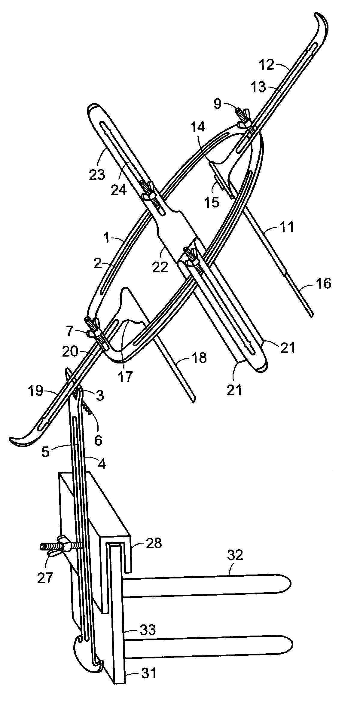
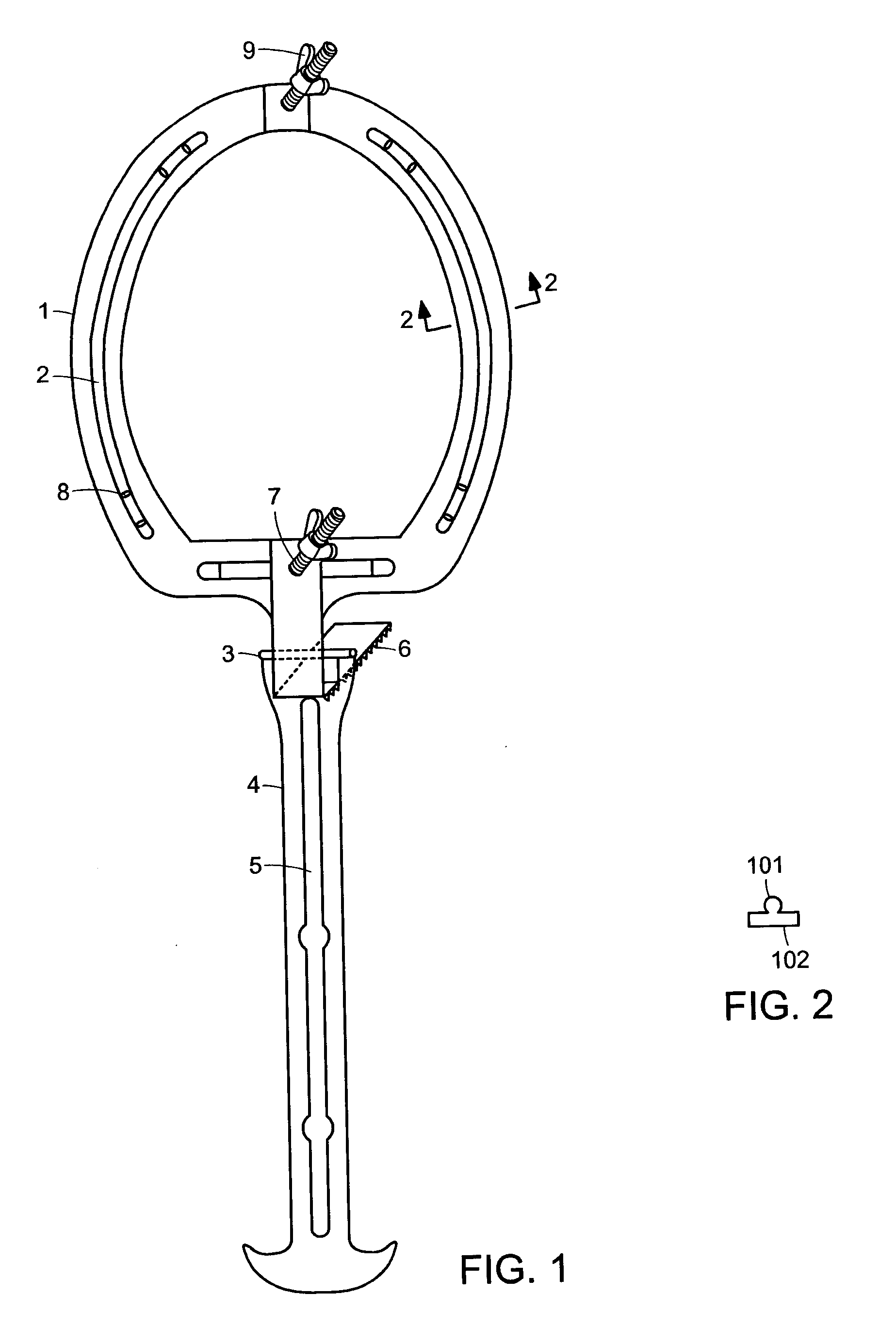
[0036] FIG. 1 shows a handle and frame of a self-retaining retractor device, according to an embodiment of the invention, that removes the need for personnel to assist a surgeon in keeping the vaginal walls or perineal incision retracted, and allows for smooth, complete retraction of the side walls, with the best possible surgical field; the device may be set up by a surgeon without assistance. A racket-shaped rigid frame 1 contains a track 2 along which a surgeon may smoothly adjust the location of a set of retractors, without the need for assisting personnel. A handle 4 is connected to the frame 1 by a hinge 3, so that the frame 1 may be moved to firmly contact the patient. A ratchet mechanism 6 near the hinge allows the angle between the frame 1 and handle 4 to be adjusted, while holding the frame 1 in place against the patient. In one embodiment according to the invention, the major axis of the frame is, for example, 14 cm. in length, while the minor axis is 12 cm. in length.

[00...


PUM


Abstract

A disclosed retraction device for gynecological surgery on a patient comprises, in one embodiment according to the invention, a frame hinged on a handle, the frame comprising a track; and at least one retractor slidably mounted on the track by a jig that does not contact the patient. The retraction device may be capable of being retained in position for surgery by the weight of the patient.

Description

[0001] The present application claims priority from U.S. Provisional Application, Serial No. 60 / 395,234, filed Jul. 11, 2002, which is incorporated herein by reference.TECHNICAL FIELD AND BACKGROUND ART[0002] The invention relates to surgical devices and methods, and in particular to devices and methods for vaginal and perineal surgery.[0003] In present techniques for vaginal surgery, it is necessary for a surgeon to be assisted by other personnel during an operation in order to retract the vaginal walls. Typically, a weight retractor is used to retract the back wall of the vagina while the assisting personnel retract the other walls of the vagina. The presence of the other personnel to assist in retraction can make the surgery more difficult by crowding the surgeon's range of motion. It may also be more costly for the surgeon, and prevent the personnel who are assisting in retraction from performing other tasks to aid in the surgery.[0004] In an embodiment of the invention, a retra...

Claims


Application Information

Patent Timeline
Patent Type & Authority Applications(United States)
IPC IPC(8): A61B17/02A61B17/42A61B19/00
CPCA61B17/02A61B19/26A61B17/42A61B17/0293A61B90/50
Inventor FANOUS, REFAAT S.
Owner FANOUS REFAAT S
Why Eureka
Try Eureka