Aircraft wheels having vanes

a technology of aircraft wheels and valences, which is applied in the direction of wheel arrangements, aircrafts, transportation and packaging, etc., can solve the problems of tire loss, tire rubber loss, and high stress on aircraft tires, and achieve the effect of reducing the risk of slipping, and reducing the safety of passengers

Inactive Publication Date: 2004-04-08
SNYDER ARNOLD J
View PDF1 Cites 15 Cited by
  • Summary
  • Abstract
  • Description
  • Claims
  • Application Information

AI Technical Summary

Benefits of technology

0009] The preferred embodiment of the present invention utilizes a new aircraft tire, which employs specially shaped vanes protrudin...

Problems solved by technology

The tires of all aircraft, particularly large, heavy, fast aircraft, are subjected to high levels of stress during landings.
Modern jetliners land at speeds in excess of 150 miles per hour, and since the wheels are not turning prior to touching the runway, aircraft ti...

Method used


Image

  • Aircraft wheels having vanes
  • Aircraft wheels having vanes
  • Aircraft wheels having vanes

Examples


Embodiment Construction

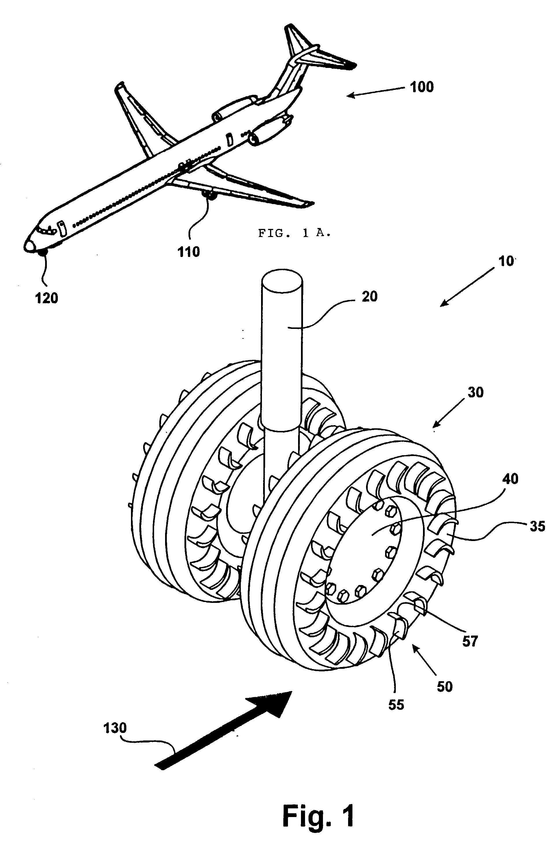
[0016] In accordance with the present invention, FIG. 1A shows a perspective view of a typical jet aircraft 100 utilizing main landing gear 110 and nose landing gear 120.

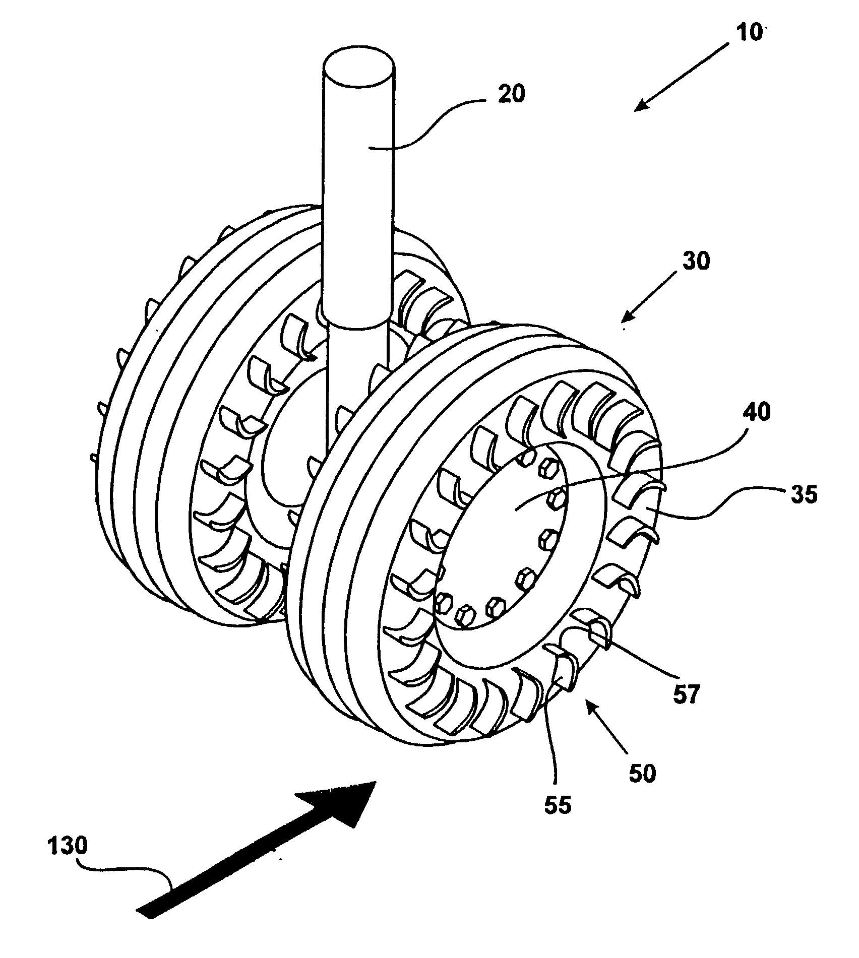
[0017] As shown in FIG. 1, the landing gear 120 has a strut 20, wheels 40, and tires 30 mounted on the wheels in a conventional manner. In the preferred embodiment, each tire 30 has a plurality of vanes 50 molded into its sidewall 35. The number, size, shape, and placement of the vanes will be determined by the particular aircraft and its landing characteristics.

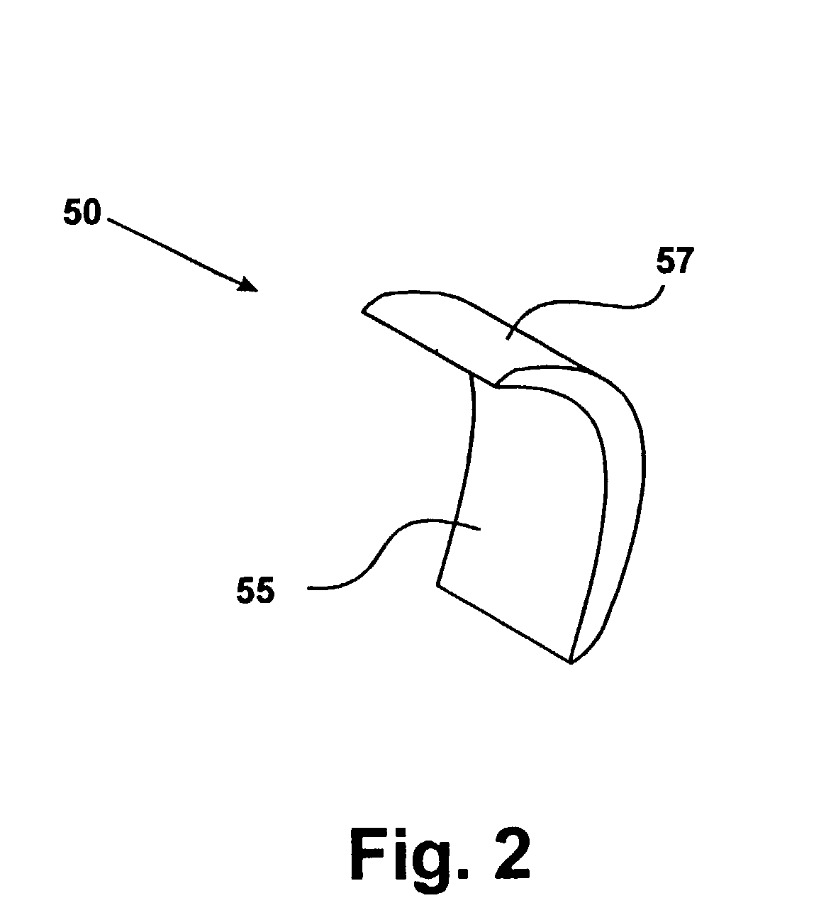
[0018] As shown in FIG. 2, each vane 50 comprises a windward face 55 and a leeward face 57.

[0019] FIG. 3 shows a second embodiment of the present invention generally at 150. Rather than utilize a new tire, ring 155 is attached to wheel 40 by means of bolts 160. Ring 155 is made of aluminum alloy, titanium alloy, steel or other durable material, and comprises a plurality of vanes 250 around its perimeter. As previously stated, the final number, size, shape, a...


PUM


Abstract

The present invention utilizes a new aircraft tire or wheel which employs specially shaped vanes protruding from the tire or wheel. These vanes capture the slipstream, and cause the tire and wheel to rotate in the direction of aircraft travel. Another embodiment of the invention employs a ring with cast or molded vanes, which may be mounted to the wheel of existing landing gear without changing to the new type of tire. The desired rotational speed of the tire will determine the number, size, and shape of the vanes, as well as how far they are mounted from the rotational axis of the tire/wheel combination.

Description

[0001] This invention relates to aircraft hardware, specifically to aircraft wheels having vanes.[0002] The tires of all aircraft, particularly large, heavy, fast aircraft, are subjected to high levels of stress during landings. Modern jetliners land at speeds in excess of 150 miles per hour, and since the wheels are not turning prior to touching the runway, aircraft tires experience very heavy forces as they come into contact with the ground. High performance military aircraft can land at even greater speeds.[0003] During landing, an aircraft tire goes from zero to over about 150 miles per hour in a very short period of time, causing it to initially "skid" as its rotational speed matches the ground speed of the aircraft. This causes the tire to lose rubber, shortening tread life. This rubber loss is often sporadic, resulting in flat spots on tires.[0004] In addition, the burned tire material can contribute to air pollution.[0005] The present invention provides a simple method and l...

Claims


Application Information

Patent Timeline
IPC IPC(8): B64C25/36B64C25/40
CPCB64C25/40B60C13/02
Inventor SNYDER, ARNOLD J.
Owner SNYDER ARNOLD J
Why Eureka
Try Eureka