Handheld planer with a chips exhausting direction changeable chip-ejecting duct
a technology of ejecting duct and hand held planer, which is applied in the direction of flat surface machines, metal-working machine components, manufacturing tools, etc., can solve the problems of difficult to achieve, not so convenient, and complicated structure of this design
- Summary
- Abstract
- Description
- Claims
- Application Information
AI Technical Summary
Benefits of technology
Problems solved by technology
Method used
Image
Examples
Embodiment Construction
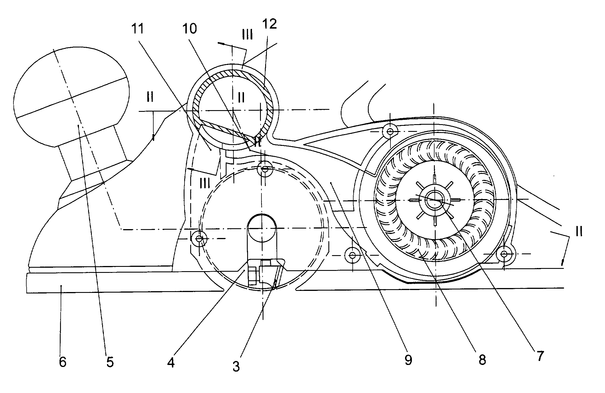
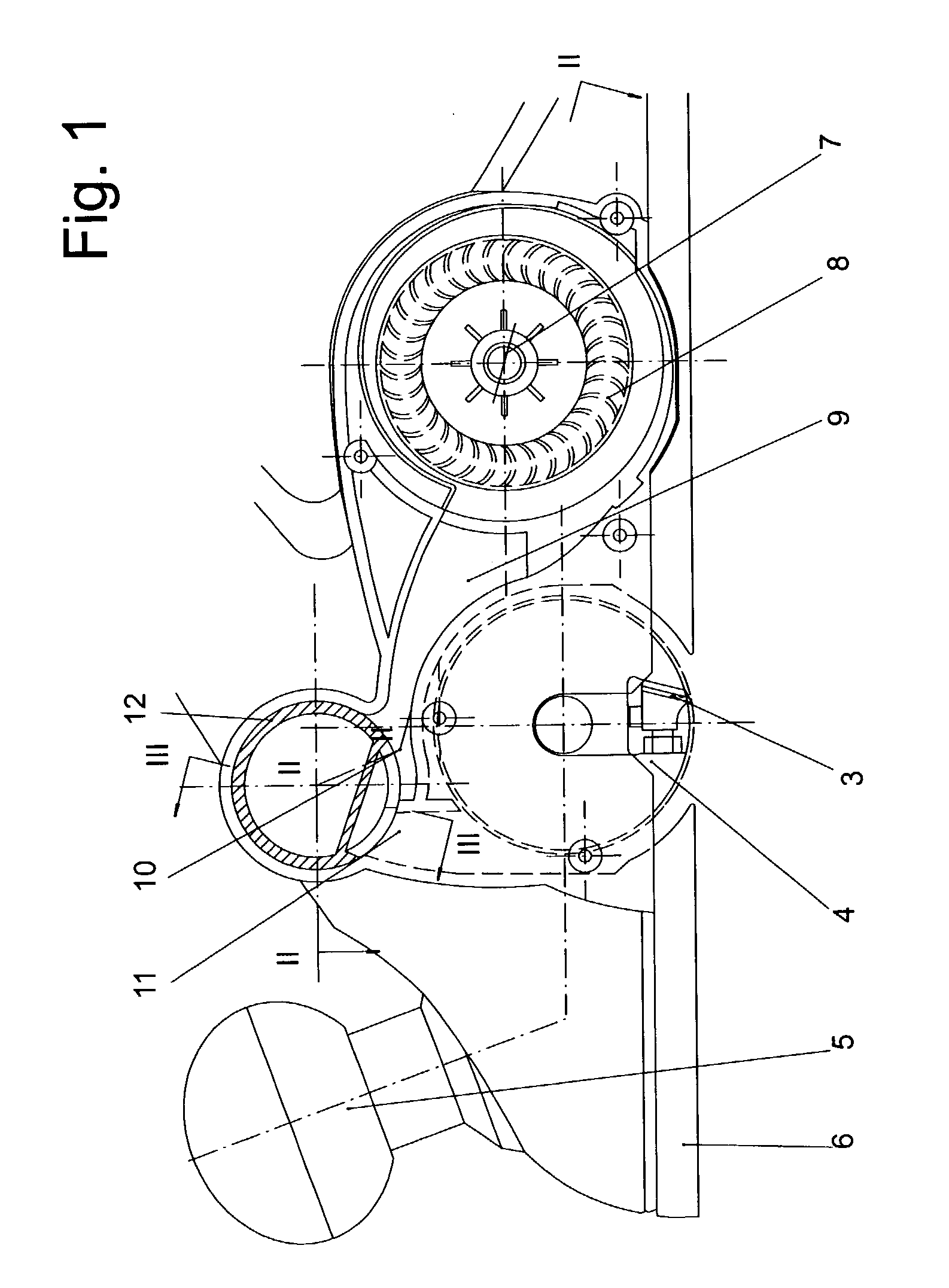
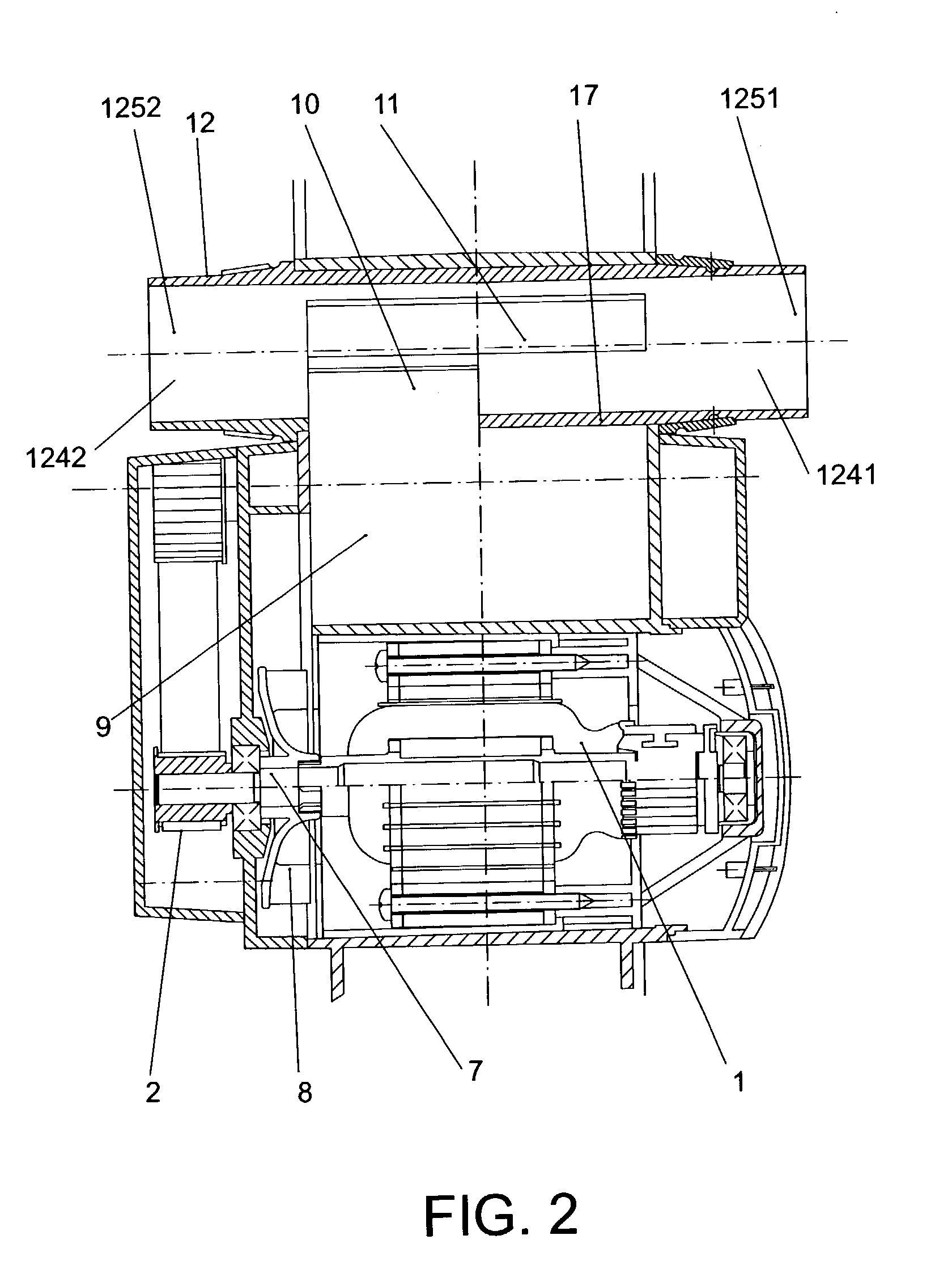
[0021] The handheld planer show in the FIG. 1 and FIG. 2, comprising: a driving motor (1), a transmission strap (2), a tool blade (3), a blade shank (4), a button (5) for adjusting cutting depth, an adjustable base (6), a motor output shaft (7), a fan (8), an air department (9), a outlet (10) for airflow out, a outlet (11) for chips out and a chip-ejecting duct (12). There is a plate (121) in the chip-ejecting duct (12), and the plate divide the chip duct into left and right departments. There are inlets (1221, 1222) (see the FIG. 3) for airflow into and inlets (1231, 1232) (see the FIGS. 3 and 4) for the chips into on the wall of the chip-ejecting duct (12). The chip-ejecting duct (12) operable connect to the planer, and can rotate about the axis of itself.
[0022] The handheld planer show in FIG. 3 and FIG. 4, there is a plate (121) in the chip-ejecting duct (12), the plate is a thin planar plate member and tilt arranged in the chip-ejecting duct (12). The upper and lower ends of th...
PUM
 Abstract
Description
Claims
Application Information
 - R&D
- Intellectual Property
- Life Sciences
- Materials
- Tech Scout
- Unparalleled Data Quality
- Higher Quality Content
- 60% Fewer Hallucinations
Browse by: Latest US Patents, China's latest patents, Technical Efficacy Thesaurus, Application Domain, Technology Topic, Popular Technical Reports.
© 2025 PatSnap. All rights reserved.Legal|Privacy policy|Modern Slavery Act Transparency Statement|Sitemap|About US| Contact US: help@patsnap.com


