Flow connector

Inactive Publication Date: 2004-04-22
CIROCCO
View PDF5 Cites 62 Cited by
  • Summary
  • Abstract
  • Description
  • Claims
  • Application Information

AI Technical Summary

Problems solved by technology

As will be appreciated, the resistance to flow of such an arrangement can be significant

Method used


Image

  • Flow connector
  • Flow connector
  • Flow connector

Examples


Embodiment Construction

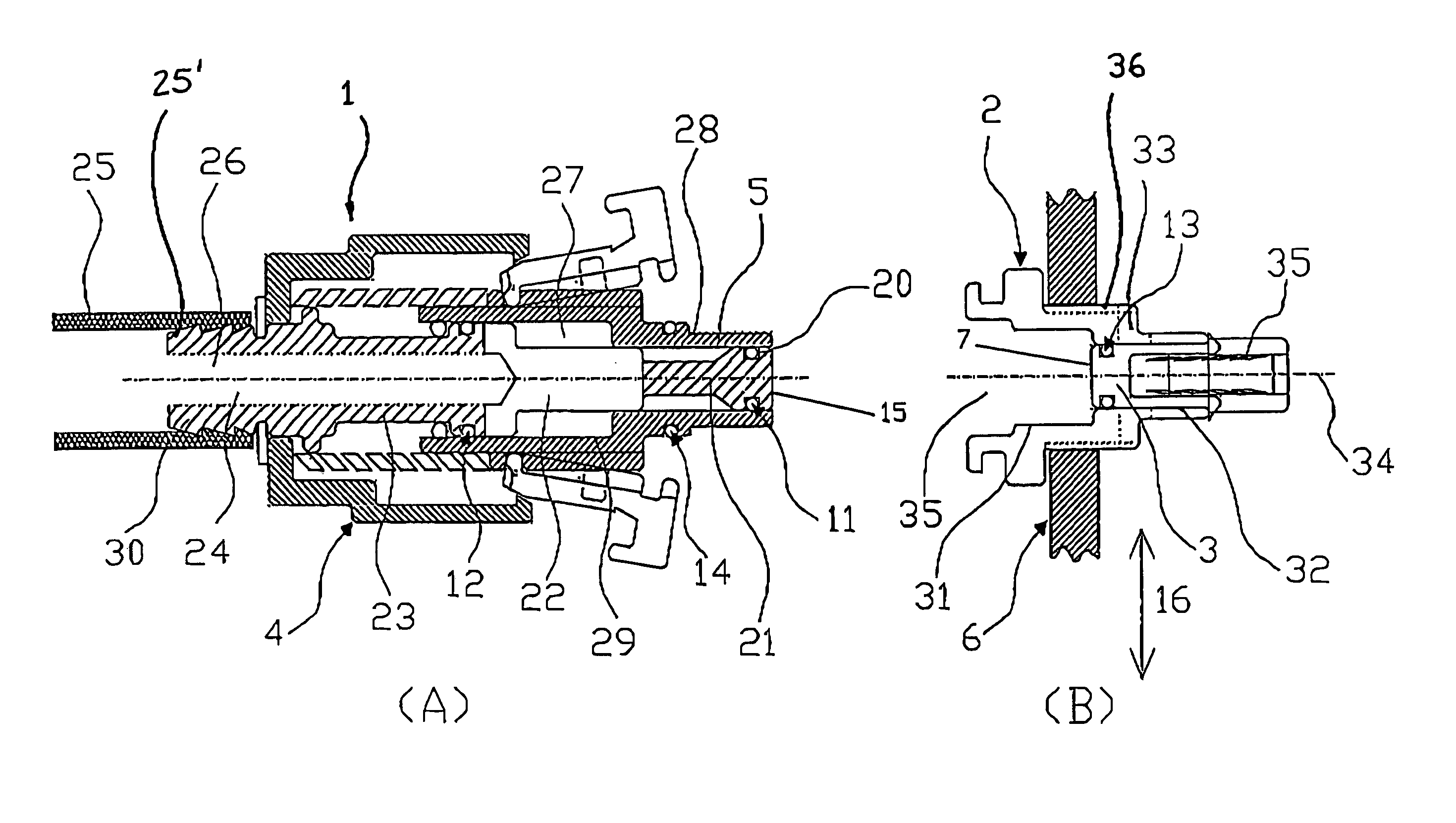
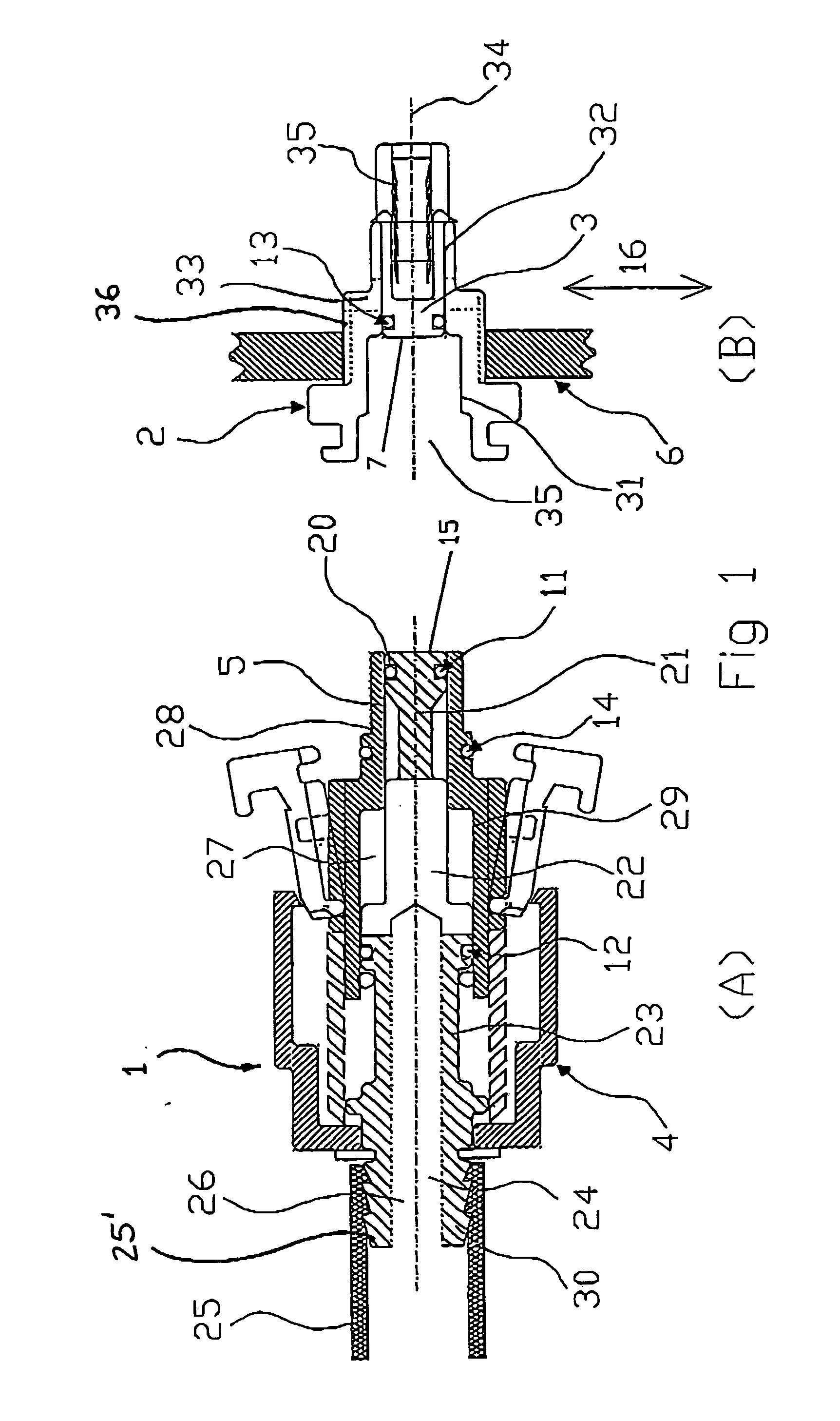
[0026] FIG. 1A shows the male component 1 of the connector and comprising a main body 5 housing a central sealing member assembly 30. Main body 5 comprises a first tubular section 28 for insertion into the female component and which is contiguous to (and preferably integral with) a wider tubular section 29. Slideably mounted within each of these two tubular sections is assembly 30, made up of a sealing member (O-ring 11) mounted in a groove 20 formed in a plunger 21. This in turn is connected by means of flat plate member 22 to tubular member 23 which is formed with a conduit 24 itself connected to an axial flow port 26. By means e.g. of a flexible pipe 25 connected to assembly 30 by means of hose barb 25', fluid is supplied through the axial flow port 26 into a chamber 27 defined by main body 5 and assembly 30. Chamber is sealed at one end by O-ring 11 bearing against the wall of the bore of tubular section 28 and at the other end by a second O-ring 12 bearing against the wall of t...


PUM


Abstract

A flow connector comprises first and second flowpath components engageable in an engagement direction. The first and second components have respective ports defining a flow path therebetween. The connector further comprises a sealing member moveable in the engagement direction between a first position between said ports and in said flow path, in which flow between said ports is prevented, and a second position not between said ports and out of said flow path, in which flow between said ports is permitted.

Description

[0001] The present invention relates to flow connectors comprising first and second flowpath components engageable in an engagement direction, in particular flow connectors comprising male and female components that interlock in an axial direction thereof, particularly flow connectors of the `dry disconnect` variety in which leakage of fluid on disconnection of the two connector components is reduced to negligible proportions or avoided completely.BACKGROUND TO THE INVENTION[0002] Connectors of this kind are known from the tanker industry where they are used to connect flexible hoses. Rotation of a handwheel screws male and female components together in an axial direction and thereafter releases sealing members in both male and female components. Fluid passes around the circumference of these sealing members on its way from an axial inlet to an axial outlet. As will be appreciated, the resistance to flow of such an arrangement can be significant, giving rise to considerable pressure...

Claims


Application Information

Patent Timeline
IPC IPC(8): F16L37/098F16L37/35
CPCH05K7/20272F16L37/121F16L37/34F16L37/32F16L37/138Y10T137/87957
Inventor SHARPE, ANDREW
Owner CIROCCO
Why Eureka
Try Eureka