Cable manufacturing method

a manufacturing method and cable technology, applied in the field of cable, can solve the problems of wire rope being susceptible to corrosion, strands may undergo plastic deformation, and rusting, and other problems, to achieve the effect of preventing rusting, preventing rusting, and preventing rusting

Active Publication Date: 2004-05-06
BRIGHT TECH CO LTD
View PDF3 Cites 33 Cited by
  • Summary
  • Abstract
  • Description
  • Claims
  • Application Information

AI Technical Summary

Problems solved by technology

Though it is stronger for a given cross section, it is also very stiff.
If a wire rope is kinked, the constituent strands may undergo plastic deformation--permanently damaging the rope.
Those skilled in the art will also know that wire rope is susceptible to corrosion, typically rusting, as well as fatigue.
It is also quite heavy.
The shorter strands can overload and break.
This causes a cascading failure as the load is carried by fewer and fewer strands.
Thus, the load-carrying ability of the stranded cable will be compromised.
The individual strands within stranded cable 10 are also often difficult to process.
Although they can be cut using a metal blade, many strands are not cut easily (NYLON and polyester being notable exceptions).
The cable as a whole will tend to smash flat or flare out under the cutting knife and deform.
1. The strands along the length of the cable can easily shift or snag during production processes, thereby causing misalignments;
2. The accurate positioning and application of a temporary localized binding mechanism (such as tape or bundling string) is difficult (explained in more detail subsequently). The length between the binding mechanism and the end of the cable is critical for properly creating the termination. Thus, the inability to accurately position the binding mechanism introduces error;
3. The addition of a localized binding mechanism causes an increased overall diameter, which may snag on machinery, feed holes, terminations, or the like;
4. A temporary localized binding mechanism is generally unable to bind the strands tightly. It is also difficult to maintain a predictable outer diameter. This fact means that bores through the terminations must be oversized. The result is a sloppy fit between the termination and the strands;
5. The individual stra

Method used


Image

  • Cable manufacturing method
  • Cable manufacturing method
  • Cable manufacturing method

Examples


Embodiment Construction

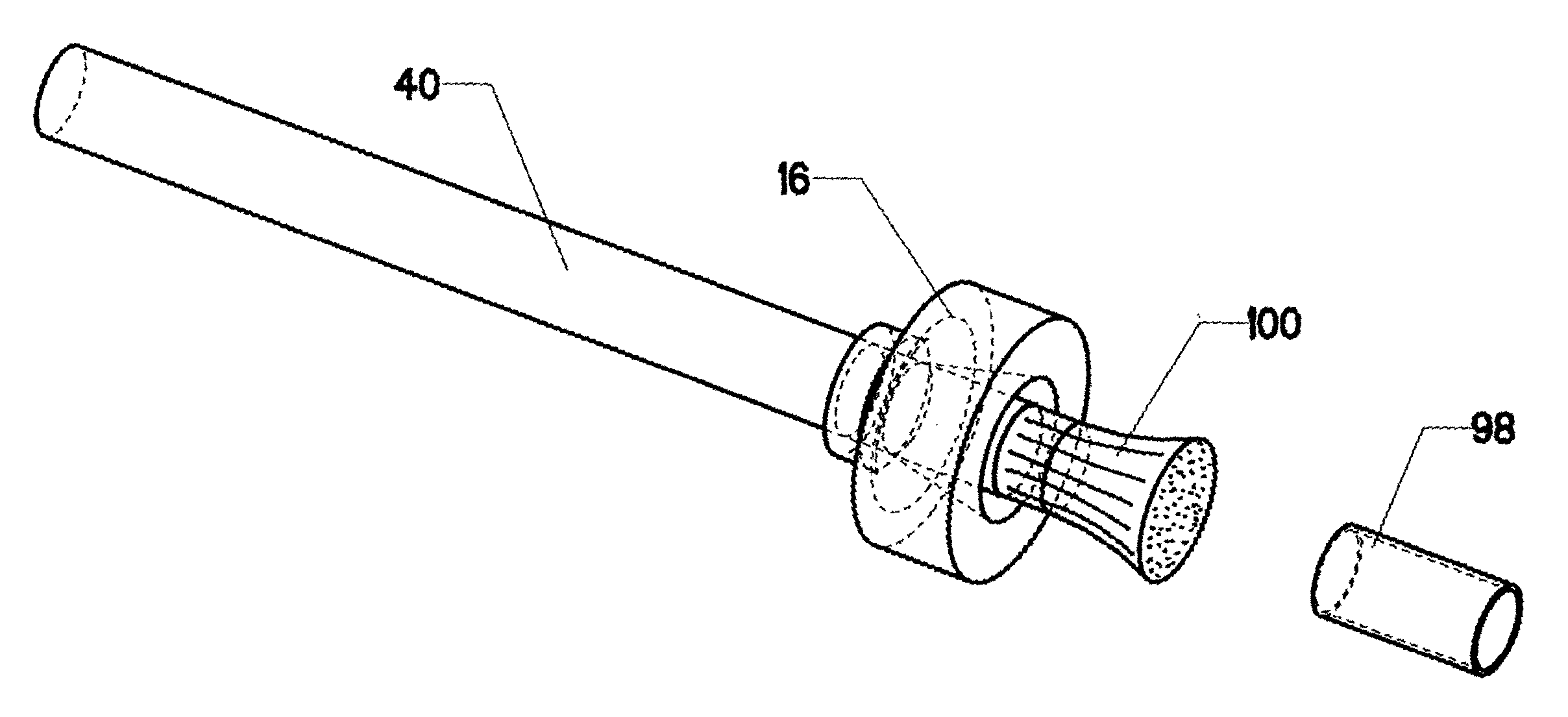
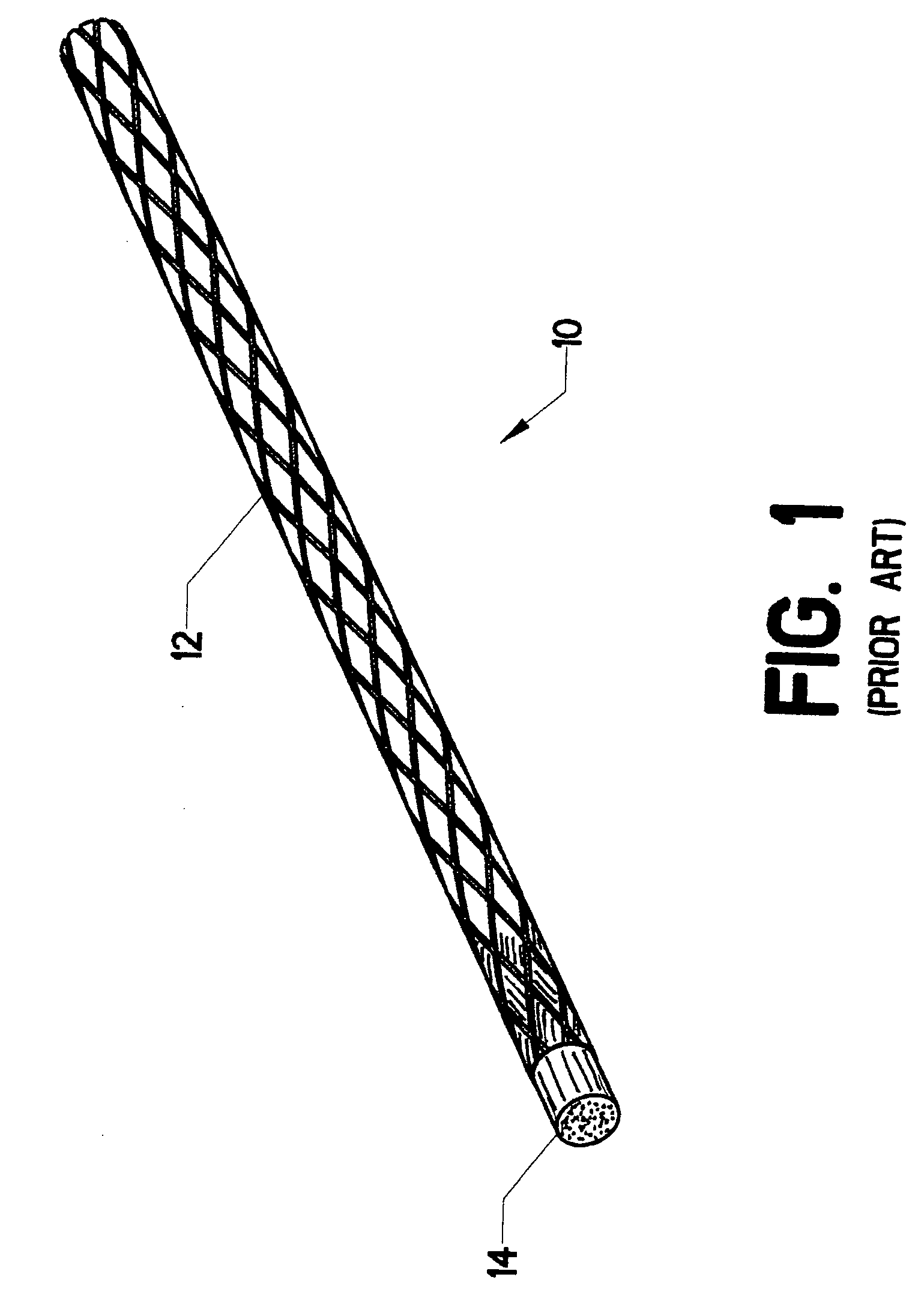
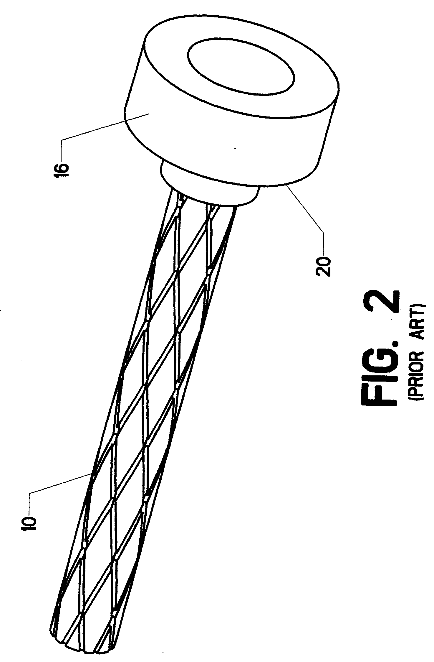
[0114] Central to this invention is the concept of enclosing stranded cable 10 with a manufacturing jacket in order to retain the strands comprising the cable in a desired state. Throughout this disclosure, it will be understood that the term "stranded cable" is used generally to describe a cable made of many strands having diameters smaller than the diameter of the stranded cable itself. The tem is intended to encompass wire rope (steel cable) as well. In other words, the term "strand" is used to describe cable constituents made of any substance, whether natural, synthetic, or metallic.

[0115] Additional definitions may be helpful to the reader. Within the art, the terms "cable" and "rope" are used to describe a tensile member made from a bundle of smaller tensile members. The terms are used interchangeably in this disclosure. Likewise, the terms "termination" and "anchor" are used in the art to describe an attaching element placed on a cable or rope (generally at one end, but somet...


PUM

PropertyMeasurementUnit
Lengthaaaaaaaaaa

Abstract

A method of manufacturing a cable assembly using stranded cable material. A manufacturing jacket is placed over the cable to hold the strands in a desired state. A length of jacketed cable is then cut to a desired length. Appropriate terminations are slipped over the manufacturing jacket on the cable's first end, its second end, or at some intermediate point. For a typical type of termination, a short portion of the manufacturing jacket is stripped away at the point of termination to expose the strands. After the terminations are placed in the appropriate position, potting compound or other mechanical means are typically applied to lock the terminations to the exposed lengths of strands. A completed cable assembly is thus created. However, the presence of the manufacturing jacket, while highly desirable for manufacturing, is often undesirable for end use. All of the manufacturing jacket, or in some instances a substantial portion thereof, is therefore removed, using a variety of disclosed methods, to form an unjacketed cable. A variety of techniques are disclosed for carrying out these steps, including the use of modified terminations and modified jackets. The finished product may have no jacket at all, a partial jacket, or a jacket which is different from the one used in the manufacturing process.

Description

[0001] 1. Field of the Invention[0002] This invention relates to the field of cables. More specifically, the invention comprises a manufacturing method which allows the automation of previously manual processes, as well as providing a superior end product.[0003] 2. Description of the Related Art[0004] Ropes and cables have been traditionally made of natural fibers or metals. These would include wire rope and hemp "hawsers." In the last half century, synthetic fibers such as NYLON and polyester have been commonly used to replace natural fibers. NYLON and polyester ropes have been used for low tension applications, whereas wire ropes (typically steel) have been used for high tension applications.[0005] Those skilled in the art will know that wire rope behaves very differently from NYLON or polyester rope. Though it is stronger for a given cross section, it is also very stiff. If a wire rope is kinked, the constituent strands may undergo plastic deformation--permanently damaging the ro...

Claims


Application Information

Patent Timeline
IPC IPC(8): B29C48/06B29C48/34B29C63/00B29C65/54B29C70/76F16G11/00
CPCB29C47/0023Y10T29/49123B29C47/28B29C63/0013B29C65/54B29C66/534B29C66/69B29C70/76B29K2105/101B29L2031/707D07B9/00D07B2201/2087D07B2201/2089F16G11/00F16G11/04B29C47/003Y10T29/49181B29C65/546B29C66/5344B29C65/48Y10T29/49192Y10T29/514Y10T29/49194Y10T29/49174B29C65/00B29C66/73715F16G11/042B29C66/71B29C66/112B29C66/116B29C66/1222B29C66/1226B29C66/131B29C66/24221B29C48/09B29C48/12B29C48/34B29C48/06B29K2067/00B29K2077/00
Inventor CAMPBELL, RICHARD VEST
Owner BRIGHT TECH CO LTD
Why Eureka
Try Eureka