
Device for fixing a functional member to a structural part of a motor vehicle, and a structural part including a portion of such a device

Inactive Publication Date: 2004-05-13
CO PLASTIC OMNIUM
View PDF13 Cites 31 Cited by
  • Summary
  • Abstract
  • Description
  • Claims
  • Application Information

AI Technical Summary

Benefits of technology

[0009] The present invention provides a device for fixing a functional member on a structural part of a motor vehicle, the device comprising a clamping spacer designed to be carried by the functional member, a clip suitable for clamping onto the spacer and capable of occupying an open position in which it frees the spacer and a closed position in which it holds it, a fixing housing carried by the structural part, suitable for containing the clip, guide means for guiding the clip in the fixing housing, enabling the clip to be inserted in part in the fixing housing and thus enabling it to be left in the open position, and subsequently enabling insertion of the clip into said fixing housing to be continued with the guide means then acting on the clip to put into its closed position.
[0031] This disposition is advantageous under circumstances when the vehicle is subjected to an impact which moves the functional member relative to the front of the vehicle. With the invention giving the structural part a certain degree of freedom to move backwards relative to the structure in which it is fixed, the functional member or its fixing purchases can escape damage and can even avoid damaging the structural member.

Problems solved by technology

However, fixing such a cooling assembly raises handling problems since the fixing means normally used require special attention on the part of the operator and require the operator to perform movements that are tiring.
To sum up, the operation of assembling the cooling assembly to the vehicle structure is lengthy and expensive.

Method used


Image

  • Device for fixing a functional member to a structural part of a motor vehicle, and a structural part including a portion of such a device
  • Device for fixing a functional member to a structural part of a motor vehicle, and a structural part including a portion of such a device
  • Device for fixing a functional member to a structural part of a motor vehicle, and a structural part including a portion of such a device

Examples


Embodiment Construction

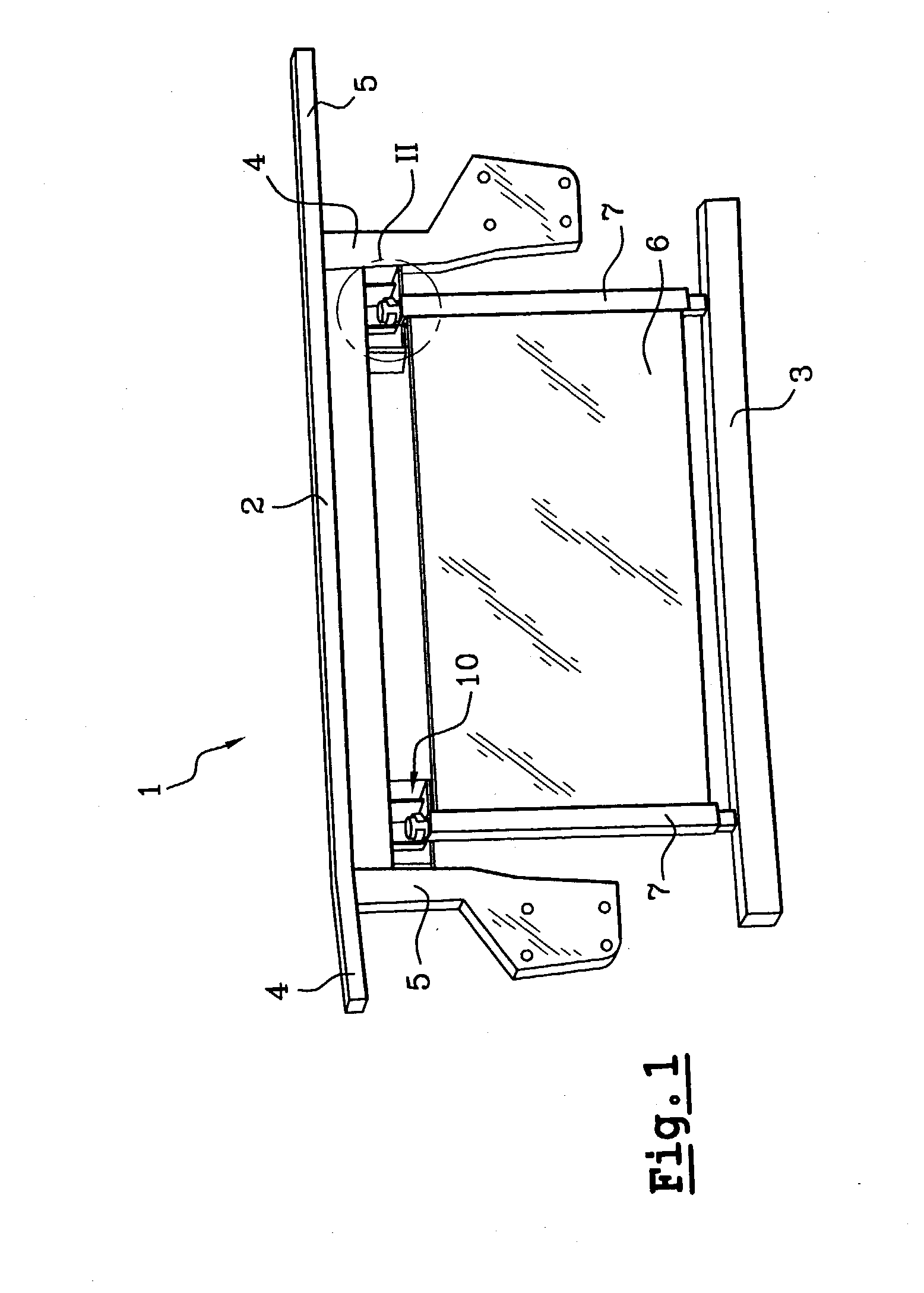
[0046] The equipment front face 1 shown in FIG. 1 is a structural part which is positioned at the front of the vehicle, above its bottom beam 3, and which includes a top cross-member 2, side support parts 4 and side legs 5.

[0047] In the context of the present description, only the top cross-member 2 is of interest, such that the example described below can be considered as applying to any structural part placed at the front of a vehicle and having a top cross-member. The structural part may indeed comprise no more than said cross-member.

[0048] A cooling assembly 6 is designed to be received vertically beneath the top cross-member 2, being supported and positioned vertically by bearing on the bottom cross-member 3, via fastener means (not shown).

[0049] In this case, the cooling assembly 6 comprises solely a radiator. In a variant, it could also include a condenser and / or a fan unit.

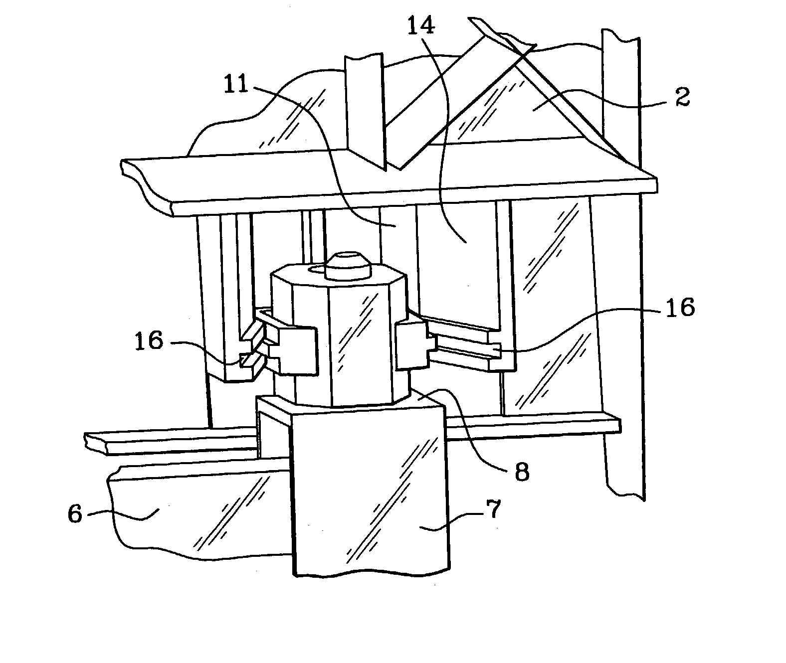
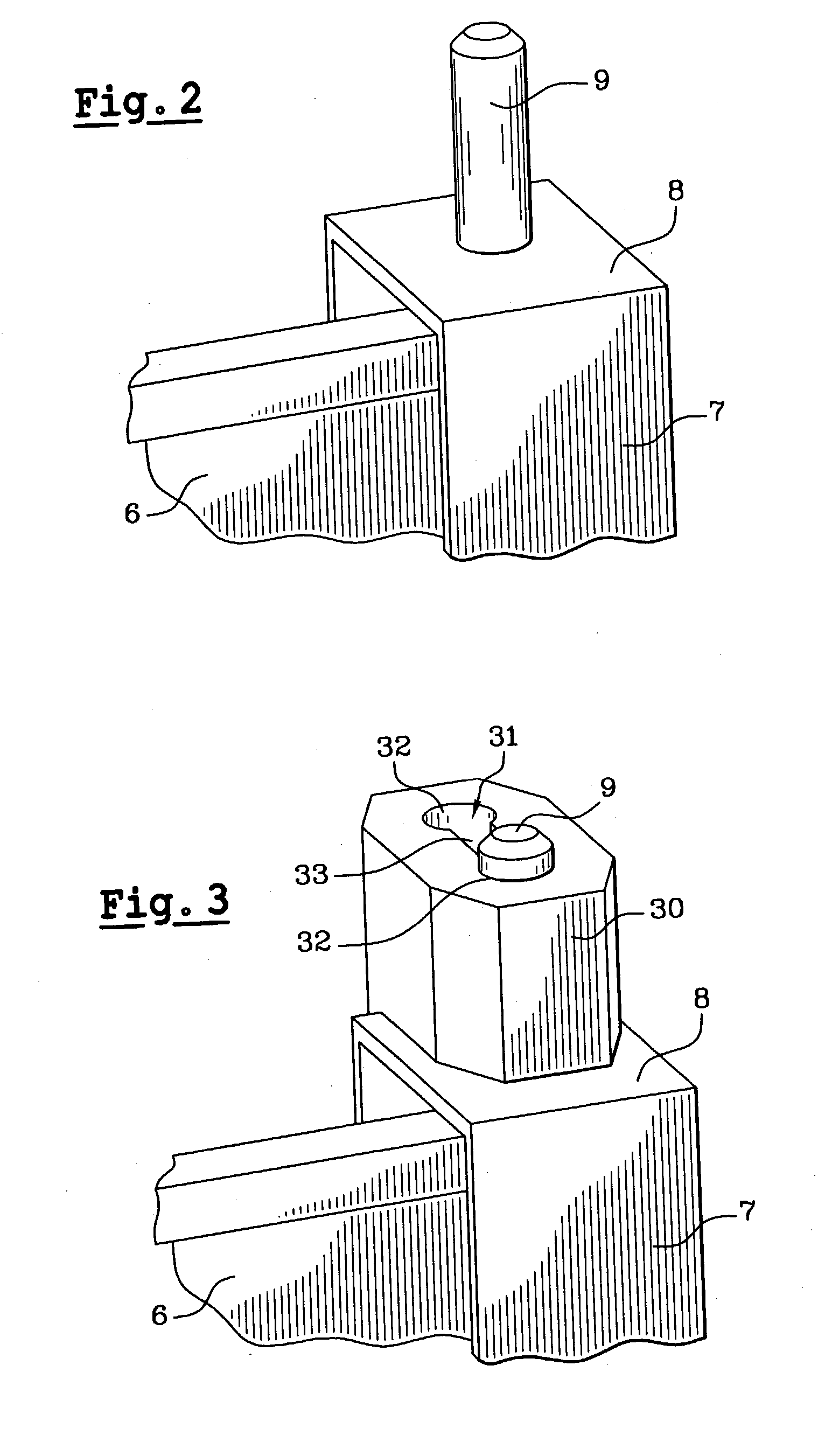
[0050] The radiator 6 supported by the bottom cross-member 3 is fixed to the top cross-member 2 by spec...


PUM


Abstract

The present invention provides a device for fixing a functional member to a structural part of a motor vehicle, the device comprising: a clamping spacer carried by the functional member; a clip suitable for clamping on the spacer and capable of occupying an open position in which it releases the spacer and a closed position in which it holds it; and a fixing housing carried by the structural part and suitable for containing the clip, means for guiding the clip in the fixing housing enable the clip to be inserted in part in the fixing housing so as to leave it in its open position, and subsequently to continue with insertion of the clip into said fixing housing, with the guide means then acting on the clip to put it into its closed position. The invention also provides a structural part and an equipment front face for a motor vehicle.

Description

[0001] The present invention relates to a device for fixing a functional member to a structural part of a motor vehicle, and also to a structural part including a portion of such a device.[0002] The front structural part of a motor vehicle supports various functional members.[0003] For example, an equipment front face is generally designed to support light units in its side portions and a cooling assembly in its central portion, i.e. a radiator and / or a fan unit and / or a condenser.[0004] However, fixing such a cooling assembly raises handling problems since the fixing means normally used require special attention on the part of the operator and require the operator to perform movements that are tiring. To sum up, the operation of assembling the cooling assembly to the vehicle structure is lengthy and expensive.OBJECTS AND SUMMARY OF THE INVENTION[0005] The present invention seeks to propose a fixing technique which, while being reliable, is also more convenient for fixing the functi...

Claims


Application Information

Patent Timeline
IPC IPC(8): B60K11/04F16B2/20F28F9/00
CPCB60K11/04F28F9/002F16B2/205
Inventor CARRIER, PASCALCHERON, HUGUESANDRE, GERALD
Owner CO PLASTIC OMNIUM
Features
  • Generate Ideas
  • Intellectual Property
  • Life Sciences
  • Materials
  • Tech Scout
  • Unparalleled Data Quality
  • Higher Quality Content
  • 60% Fewer Hallucinations
Learn More