Blocking device for a locking stressing mechanism having a spring-actuated output drive device

Active Publication Date: 2004-05-20
BOEHRINGER INGELHEIM INT GMBH
View PDF17 Cites 86 Cited by
  • Summary
  • Abstract
  • Description
  • Claims
  • Application Information

AI Technical Summary

Benefits of technology

0005] WO-93/21980 describes a metered-dose inhaler. The dose of a substance to be inhaled is introduced, by means of a hand-operated device, from a supply of the substance contained in the inhaler, into a chamber from which the dose is expelled with the current of air which the user sucks in through the inhaler as they breathe in. The metered-dose inhaler is fitted with a counter which comprises a rotatable screw spindle and a rod, one end of which engages in the form of a nose in the thread of the screw spindle. The rod moves parallel to the screw spindle as the rotation of the spindle increases. The counter indicates, by means of the position of the nose-like end of the rod, the number of doses which hav

Problems solved by technology

The activated blocking device which contains a pre-stressed metal leaf spring can only be overc

Method used


Image

  • Blocking device for a locking stressing mechanism having a spring-actuated output drive device
  • Blocking device for a locking stressing mechanism having a spring-actuated output drive device
  • Blocking device for a locking stressing mechanism having a spring-actuated output drive device

Examples


Example

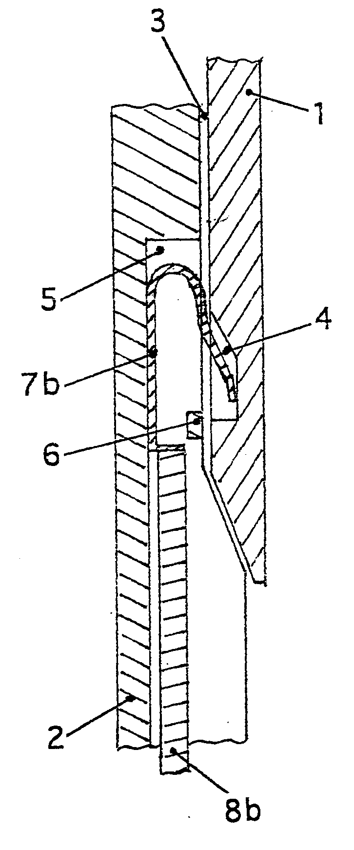
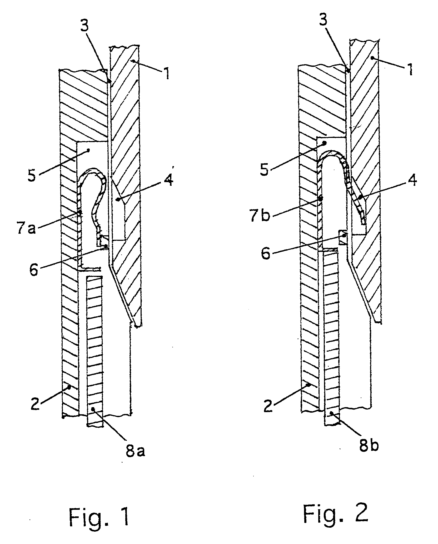
[0032] A preferred embodiment of the blocking device according to the invention will be explained in more detail with reference to the figures. FIGS. 1 and 2 show partial longitudinal sections through the wall of the lower and upper housing part as well as a leaf spring as a blocking element and a push rod level with the recesses in the walls. The longitudinal section runs parallel to the axis of the lower and upper housing parts.

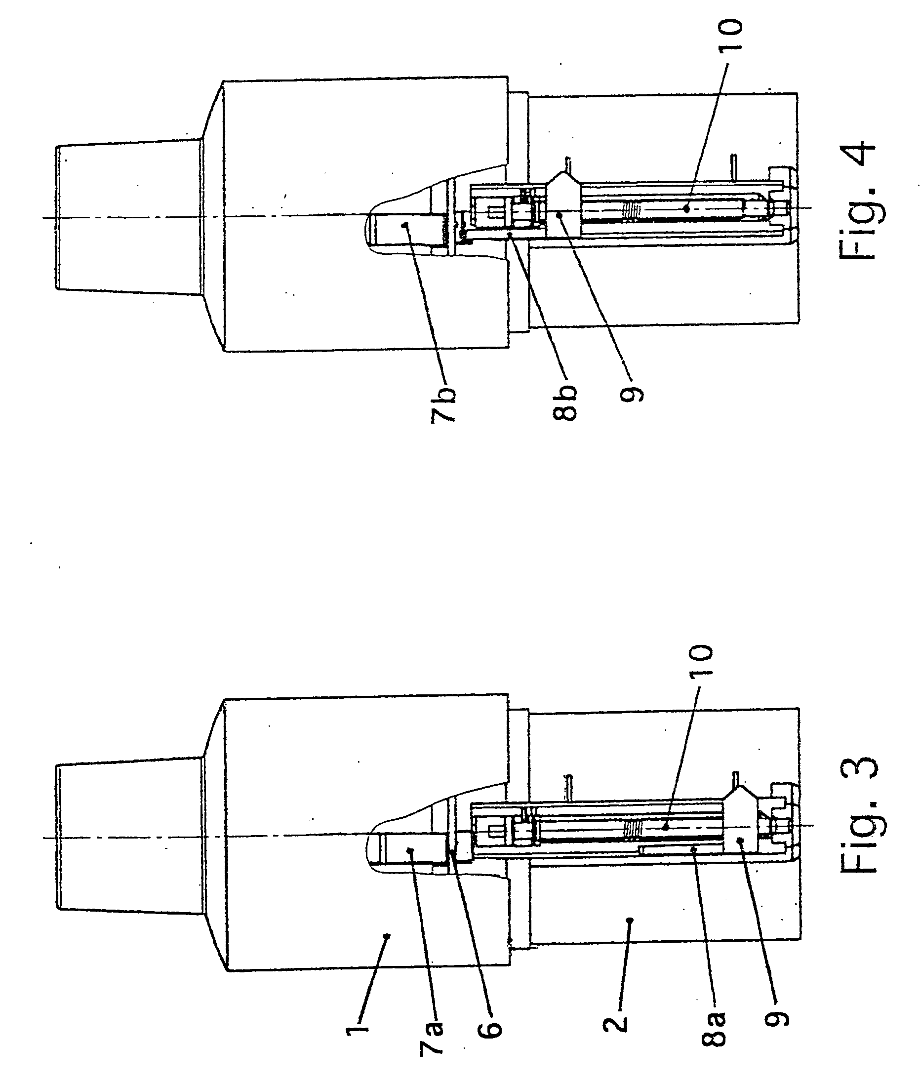
[0033] FIGS. 3 and 4 show a longitudinal elevation of a device cut open in the region of the counter and the blocking device.

[0034] In FIGS. 1 and 3 the blocking device is shown in the resting position. The blocking element is in its resting position and is located only in the recess in the wall of the lower housing part. FIGS. 2 and 4 show the blocking device activated. The blocking element has been moved out of its resting position and is located in both recesses in the walls of the two housing parts.

[0035] The upper housing part (1) overlaps the lower ho...


PUM


Abstract

A locking-stressing-mechanism with spring-actuated output drive and a counter with which an apparatus of this kind is fitted, accommodated in a two part housing the two parts of which are mounted to be rotatable relative to each other, can be blocked by means of a pre-stressed leaf spring. The leaf spring is initially accommodated in a recess in the wall of one housing part. As soon as the permitted number of actuations has been reached a push rod pushes the leaf spring out of its resting position. The leaf spring then jumps into a recess in the wall of the other housing part and the two housing parts can no longer be rotated relative to each other. The push rod may be mounted on the pointer of the counter. This blocking device can only be overcome by the application of a force which is sufficient to destroy the device. The device is suitable for blocking a high pressure atomiser or a needleless injector with which a fluid is atomised to form an aerosol or a fluid is injected into a biological tissue.

Description

[0001] The priority benefit of DE 10239443.1, filed Aug. 28, 2002 and U.S. Provisional Application No. 60 / 458,212, filed Mar. 27, 2003 are hereby claimed, both of which are incorporated by reference herein.[0002] The invention relates to a blocking device by means of which the proper use of a device equipped with a locking-stressing mechanism and a spring-actuated output drive is prevented after a given number of actuations. The device may be, for example, a high pressure atomiser or a needleless injector.BACKGROUND AND DESCRIPTION OF THE INVENTION[0003] The aim of the invention is to reliably limit the period of use of such a device and meet safety requirements. The reasons for the limitation may be based on hygiene, medical or technical considerations.[0004] The locking-stressing-mechanism, which is to be blocked after the permitted period of use has elapsed preferably comprises a helical thrust gear accommodated in a manually operated device, by means of which a rotary movement i...

Claims


Application Information

Patent Timeline
IPC IPC(8): A61M5/30A61M5/50A61M15/00B05B11/00
CPCA61M15/00A61M2205/273B05B11/308A61M15/0068A61M5/30A61M5/50B05B11/3091A61M15/0081B05B11/108B05B11/1091
Inventor SCHYRA, MICHAELWACHTEL, HERBERT
Owner BOEHRINGER INGELHEIM INT GMBH
Why Eureka
Try Eureka