System and method for creating a representation of an assembly

a technology of creating a representation and an assembly, applied in the direction of cad techniques, configuration cad, instruments, etc., can solve the problems of increasing complexity of assemblies, inefficient use of time, money and expertise, and inventing the wheel

Inactive Publication Date: 2004-05-20
QSSOLUTIONS +1
View PDF23 Cites 63 Cited by
  • Summary
  • Abstract
  • Description
  • Claims
  • Application Information

AI Technical Summary

Problems solved by technology

Reinventing the wheel is an inefficient use of time, money, and expertise.
Such a technique becomes increasingly ineffective as the assemblies increase in complexity.
Furthermore, such a process is not automated, requiring the designer to locate a suitable template, and then go about the process of building the alternative design.
However, the prior art does not disclose such a system.

Method used


Image

  • System and method for creating a representation of an assembly
  • System and method for creating a representation of an assembly
  • System and method for creating a representation of an assembly

Examples


Embodiment Construction

I. Introduction of Elements

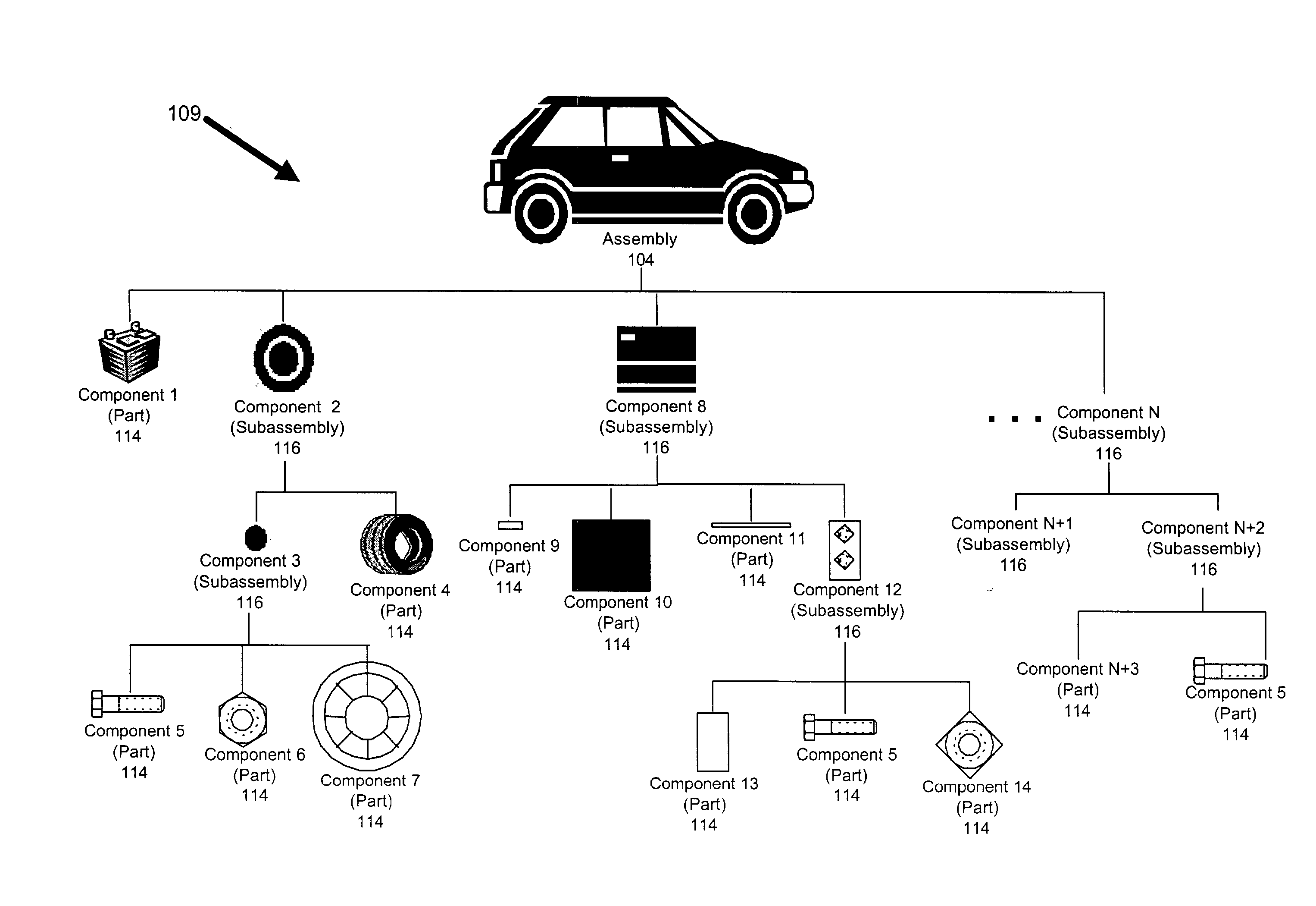
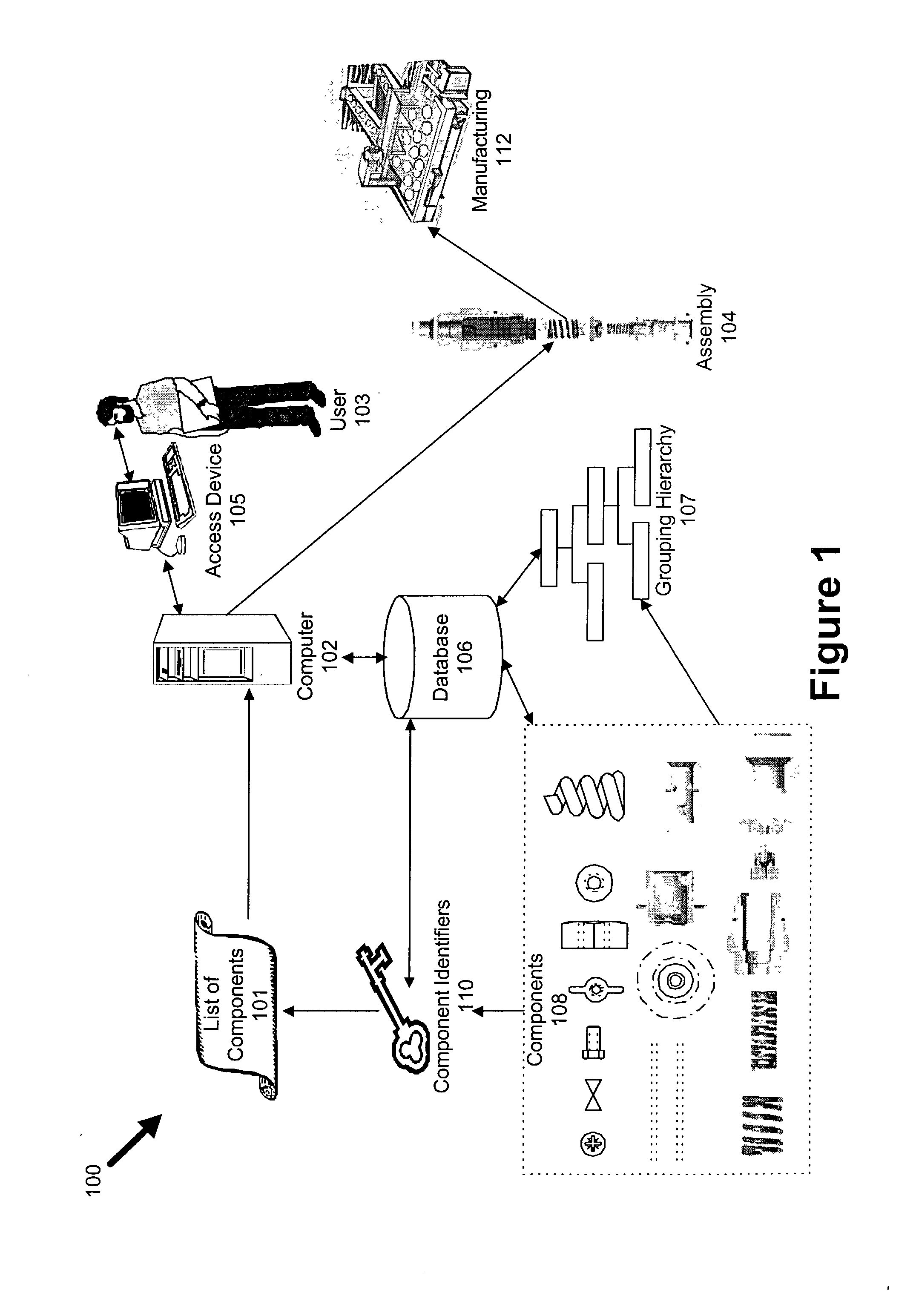
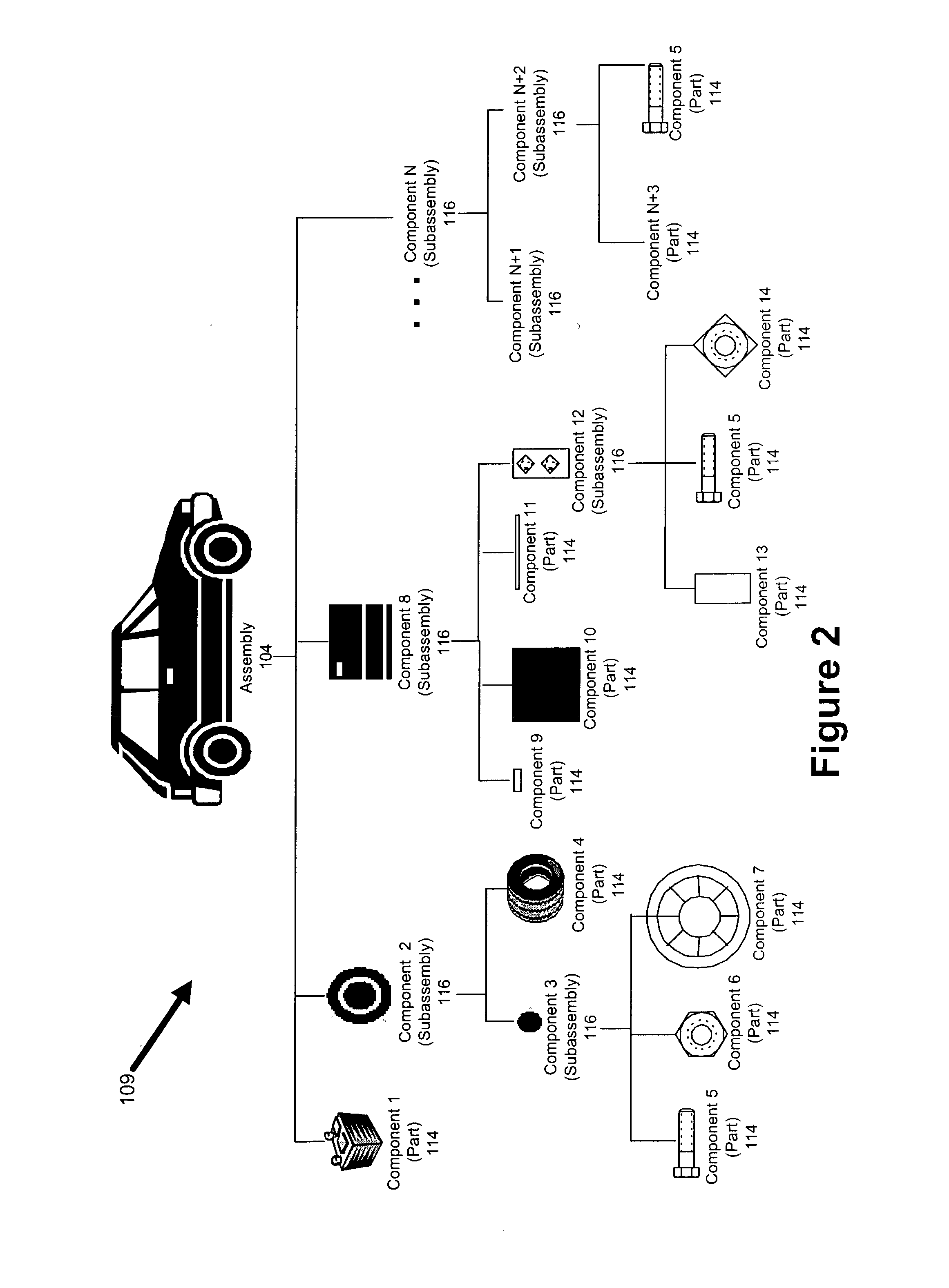
[0033] FIG. 1 is a block diagram illustrating an example of some of the elements that can be incorporated into a system and method (collectively the "drawing system" or simply the "system") 100 for creating a drawing, model, or other form of representation (collectively a "drawing") of an assembly 104. The system 100 can create a drawing of the assembly 104 from a list of components 101, such as a bill of material. Unless otherwise specifically designated as "physical" or "manufactured" structures, all references to components, parts, subassemblies, assemblies, component groups, and other structures (collectively "structures") refer to drawings of such structures, and not the "physical" structure represented by the drawing. Similarly, any reference to a characteristic of a structure refers to a characteristic of the structure as represented in the system 100, unless the structure is specifically designated as a "physical" or "manufactured" structure.

[0034]...


PUM


Abstract

The invention is a system or method (collectively the "drawing system" or simply "system") for automatically creating a drawing, model, or other type of representation (collectively a "drawing") of an assembly from a list of component parts. The system can use a list of components, a hierarchy of assembly components, and a hierarchy of component groups, to automatically create a drawing of an assembly. The system can also be configured to automatically create a drawing of an assembly from a bill of materials and a database of components. The system can be implemented through various combinations of subsystems.

Description

BACKGROUND OF INVENTION[0001] The invention relates generally to tools and techniques for creating a representation of an assembly. More specifically, the invention relates to a system and method (collectively "drawing system" or simply the "system") for automatically creating a drawing, model or other representation (collectively "representation") of an assembly from a list of components, such as parts and / or subassemblies.[0002] The use of Computer Aided Design ("CAD") techniques and other design tools (collectively "CAD tools") is widespread. Engineers in a wide variety of different manufacturing and other industries utilize CAD tools to design assemblies. Product designs of assemblies are typically generated using CAD tools, regardless of whether the assembly is an airplane, an automobile, a dishwasher, industrial equipment, or any other type of engineered or manufactured product. When it is necessary for design information to be exchanged between employees in the same company, ...

Claims


Application Information

Patent Timeline
Patent Type & Authority Applications(United States)
IPC IPC(8): G06F17/50G06F19/00G06T17/00
CPCG06F17/50G06T17/005G06F2217/02G06F30/00G06F2111/20
Inventor CARLUCCI, ARTHUR C.KANNEGANTI, VANKATESHKELLY, THOMAS W.GEENHOVEN, CHAD VAN
Owner QSSOLUTIONS
Why Eureka
Try Eureka