
Distal tip for the positioning of artificial joint stem

a technology of distal end and positioning tip, which is applied in the direction of shoulder joints, prostheses, osteosynthesis devices, etc., can solve the problems of osteolysis and loosening of artificial joints, pain and/or bone fracture, and difficulty in precisely positioning the distal end portion of the stem

Inactive Publication Date: 2004-06-03
SENKO MED INSTR MFG CO LTD
View PDF1 Cites 24 Cited by
  • Summary
  • Abstract
  • Description
  • Claims
  • Application Information

AI Technical Summary

Benefits of technology

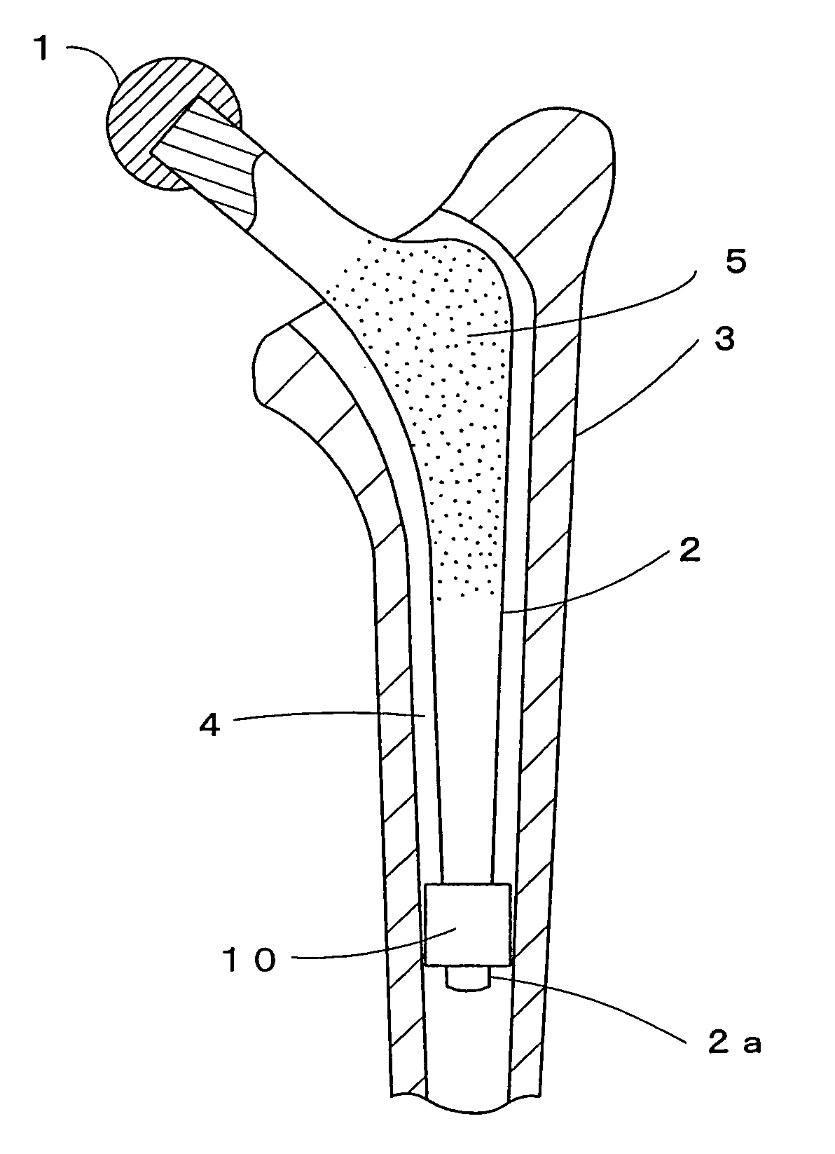
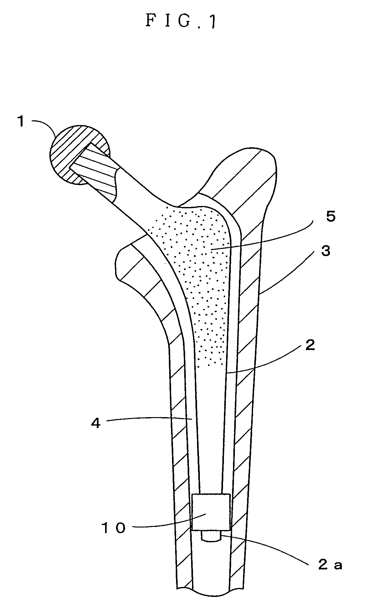
The present invention provides a distal tip for positioning the stem of a cementless artificial joint that can reliably guide the insertion of the stem and prevent osteolysis and loosening of the artificial joint that has been taking place in the prior art. The distal tip is designed to maintain the entire stem in a predetermined posture in the bone canal and can be used in both cemented and cementless types of artificial joints. The distal tip is designed to evenly distribute the load on the bone and prevent concentration of stress at the contact point with the bone, which can cause osteolysis and loosening of the artificial joint.

Problems solved by technology

Since the bone canal has anatomical curve, however, distal end of the artificial hip joint stem comes into contact with the bone inside the bone canal to cause concentration of stress at the contact point, resulting in osteolysis which leads to loosening of the artificial joint, pain and / or bone fracture.
However, the stem which becomes thinner toward the distal end makes it difficult to precisely locate the narrower distal end portion of the stem at the center of the bone canal when inserting the stem into the bone canal, and the stem angle tends to take a varus position, valgus position, anteversion position or retroversion position in the bone canal.
This situation also leads to osteolysis and loosening of the artificial joint.
With this method, however, the distal tip mounted on the stem comes into contact with the bone to cause concentration of stress at the contact point, again resulting in osteolysis and loosening of the artificial joint.
With the artificial joint of cementless type, as described above, although it is made easier to position the distal end portion of the stem at the center of the bone canal by mounting the distal tip on the stem of the artificial joint, the distal tip makes contact with the bone over a long period of time so as to cause concentration of stress, thus resulting in osteolysis and loosening of the artificial joint.

Method used


Image

  • Distal tip for the positioning of artificial joint stem
  • Distal tip for the positioning of artificial joint stem
  • Distal tip for the positioning of artificial joint stem

Examples


Embodiment Construction

[0048] In order to achieve the object described above, first feature of the present invention is a distal tip for the positioning of artificial joint stem, that is mounted near the distal end portion of stem of the cementless artificial joint thereby to guide the distal end portion of the stem so as not to make direct contact with the inner surface of the bone canal when the stem of the artificial joint is inserted into the bone canal, and make stable positioning of the stem distal end portion when the insertion of stem is completed, wherein the distal tip is made of a biodegradable and absorbable material.

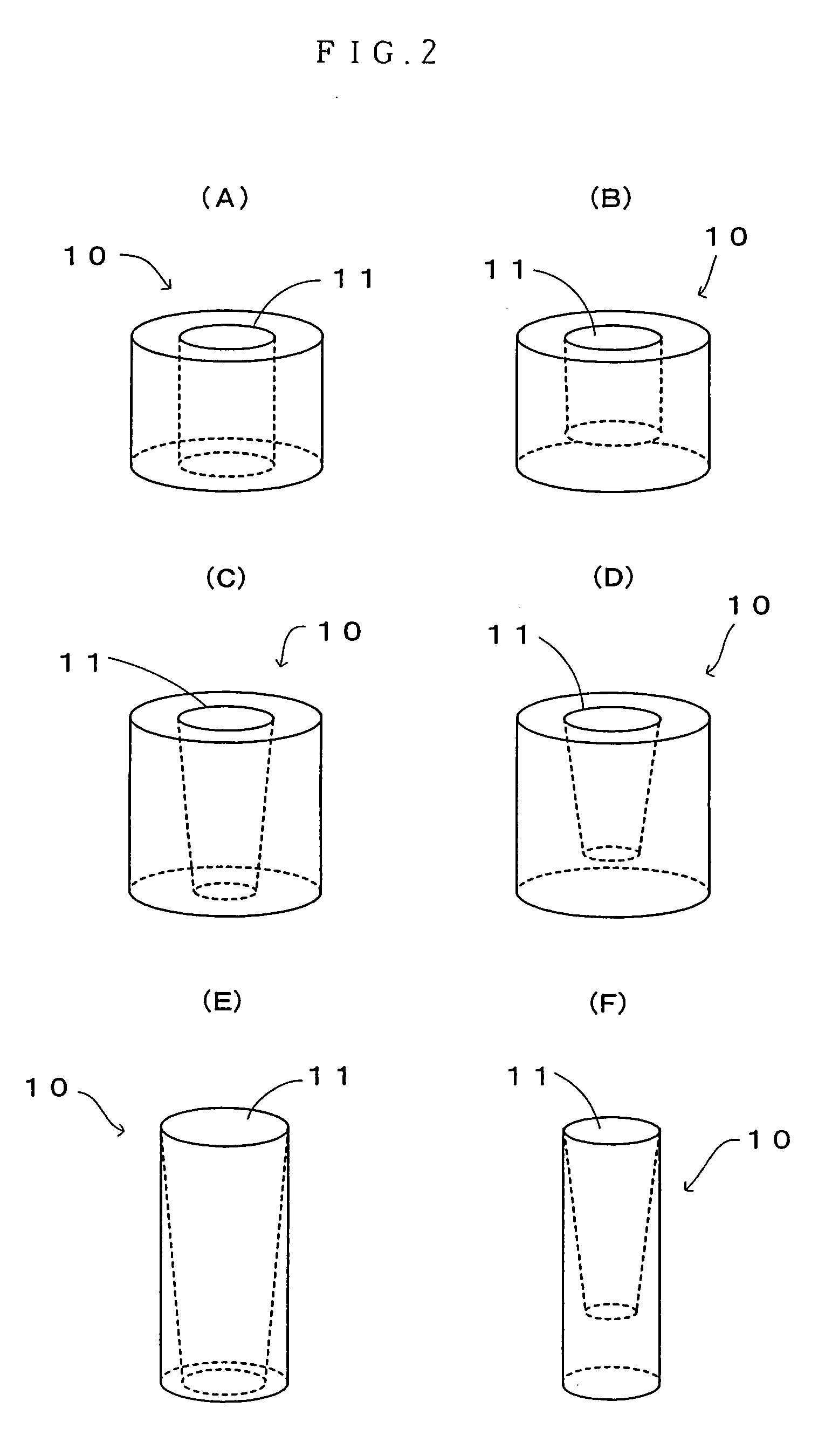
[0049] Second feature of the distal tip for positioning of artificial joint stem of the present invention is, in addition to the first feature, that the distal tip is made in such a configuration as the diameter of the horizontal section thereof is larger than the diameter of the horizontal section of the stem near the distal end thereof, and the distal tip is provided with mounti...


PUM

PropertyMeasurementUnit
angleaaaaaaaaaa
absorbableaaaaaaaaaa
diameteraaaaaaaaaa

Abstract

The present invention provides a distal tip for the positioning of artificial joint stem that is capable of reliably guiding the insertion of the stem of the cementless artificial joint into a bone canal and positioning the distal end portion of the stem that is inserted into the bone canal at a planned position, thereby to maintain the entire stem in a favorable posture in the bone canal, and prevent osteolysis and loosening of the artificial join even when the distal tip is used. The distal tip 10 for the positioning of artificial joint stem is mounted near the distal end portion 2a of the stem of the cementless artificial joint thereby to guide the distal end portion 2a of the stem so as not to make direct contact with the inner surface of the bone canal 4 of the bone 3 when the stem 2 of the artificial joint is inserted into the bone canal 4, and make stable positioning of the stem distal end portion 2a when the insertion of the stem 2 is completed, wherein the distal tip 10 is made of a biodegradable and absorbable material.

Description

[0001] 1. Field of the Invention[0002] The present invention relates to a distal tip for the positioning of artificial joint stem and, more particularly, to a distal tip for the positioning of a stem used in a cementless artificial joint.[0003] 2. Description of Related Art[0004] Artificial joints can be roughly divided into a cemented artificial joint which is inserted in a bone canal that is filled with cement so that clearance between the bone and the stem of the artificial joint inserted therein is filled and fixed with the cement, and an artificial joint of cementless type that is designed for directly joining the stem of the artificial joint with the bone.[0005] In the case of artificial joint of cementless type, stable connection of the artificial joint and the bone is achieved by joining with cancellous bone in the proximate portion of the stem, although the cancellous bone takes several months to grow at the earliest.[0006] When an artificial joint of cementless type is app...

Claims


Application Information

Patent Timeline
Patent Type & Authority Applications(United States)
IPC IPC(8): A61F2/00A61F2/02A61B17/58A61F2/30A61F2/36A61F2/38A61F2/40A61F2/42A61F2/46A61L27/58
CPCA61F2/30724A61L27/58A61F2/367A61F2/3676A61F2/38A61F2/3804A61F2/4202A61F2/4241A61F2/4261A61F2002/30062A61F2002/30112A61F2002/30115A61F2002/30121A61F2002/30146A61F2002/3021A61F2002/30224A61F2002/30235A61F2002/30322A61F2002/30326A61F2002/30332A61F2002/30354A61F2002/30359A61F2002/30377A61F2002/3038A61F2002/30403A61F2002/30405A61F2002/3054A61F2002/30542A61F2002/30772A61F2002/30795A61F2002/30797A61F2002/30886A61F2002/30894A61F2002/3611A61F2002/3625A61F2002/365A61F2002/3664A61F2002/4077A61F2210/0004A61F2220/0025A61F2220/0033A61F2230/0004A61F2230/0006A61F2230/0017A61F2230/0067A61F2230/0069A61F2250/0026A61F2250/0037A61F2310/00011A61F2310/00017A61F2310/00023A61F2310/00029A61F2310/00293A61F2/36A61F2002/30367A61F2002/30331A61F2002/30878
Inventor KATSUYA, TOSHINOBU
Owner SENKO MED INSTR MFG CO LTD
Learn More