
Paramagnetic liquid interface

a liquid interface and paramagnetic technology, applied in the field of joints, can solve the problems of damping energy transmission, inherent friction and wear characteristics, wear and loosening of the tjr components, further arthritic changes of the joint itself, etc., and achieve the effects of enhancing the rheological properties of the ves, enhancing the duration of the pharmacological properties of the has, and not affecting the safety of the has

Inactive Publication Date: 2007-05-03
HYDE EDWARD R JR
View PDF16 Cites 48 Cited by
  • Summary
  • Abstract
  • Description
  • Claims
  • Application Information

AI Technical Summary

Benefits of technology

[0006] Lubrication between component surfaces is by fluids naturally produced by the joint. This lubrication reduces some of the inherent friction and wear characteristics and damps energy transmission. Wetting of surfaces is also important to natural joint function to provide smooth transition of energy into motion.
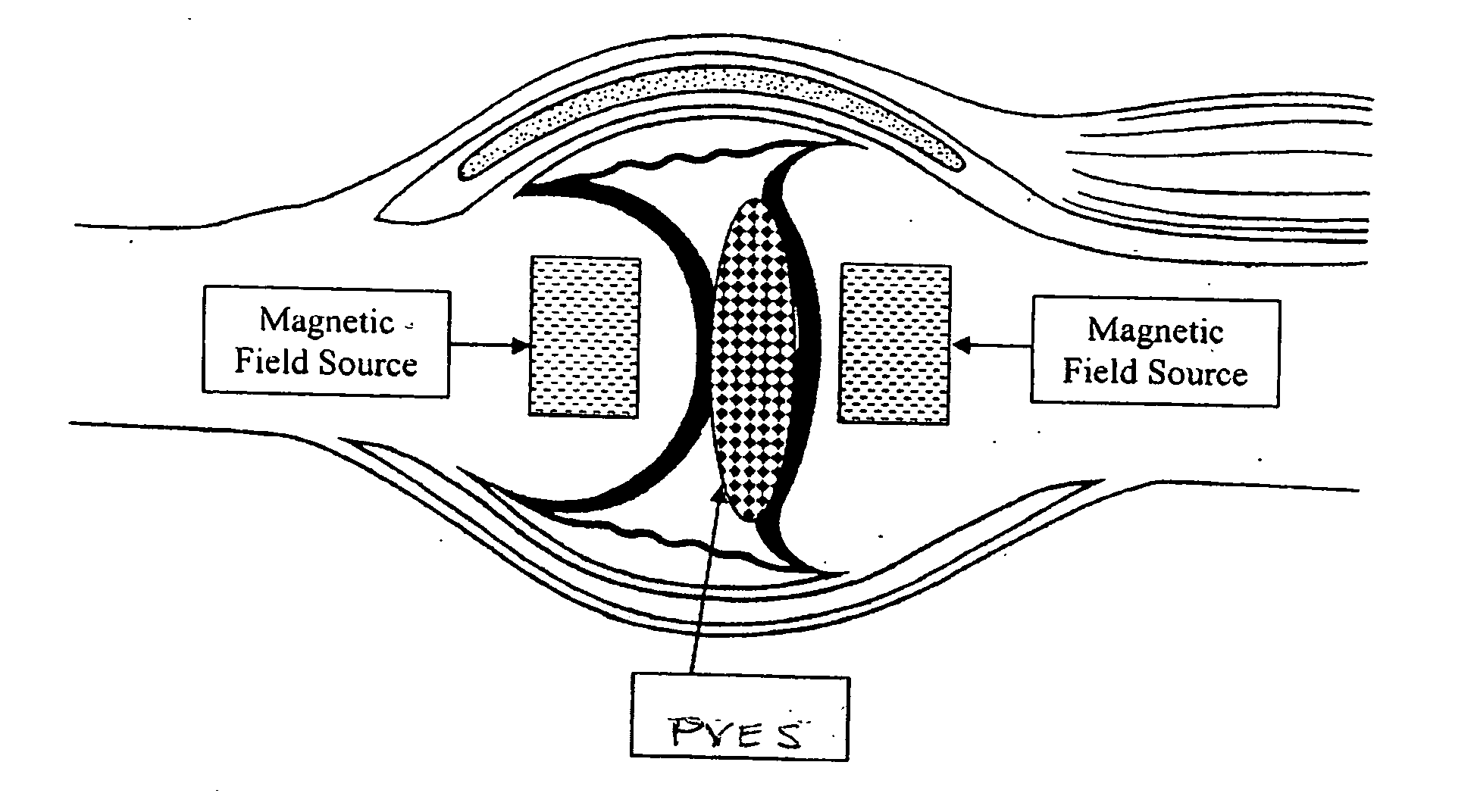
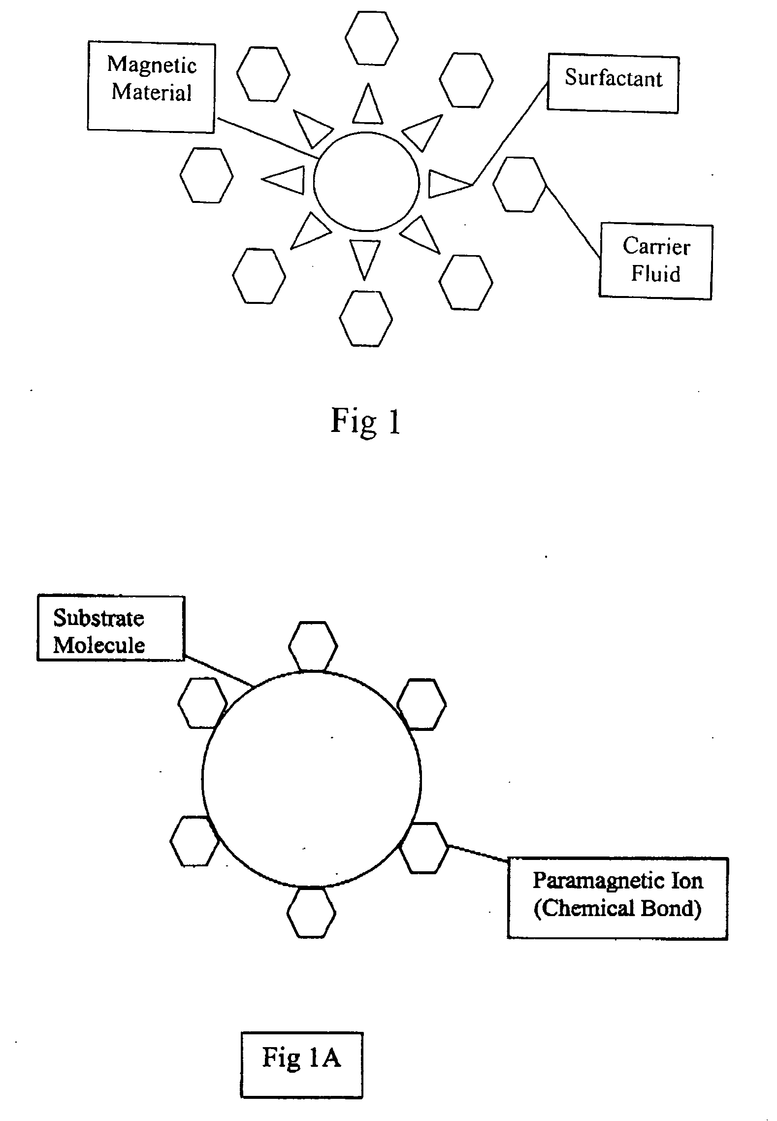
[0028] The addition of paramagnetic ions to a HAS or any alternative visco-viscoelastic supplement (VES) will allow the VES to be affected by a magnetic field. The magnetic field can be used to localize and concentrate the VES. The magnetic field also introduces energy into the VES that produces a force capable of doing work. This force resists the disbursement of the VES by mechanical forces. The magnetic field can also have a magneto-rheological effect on the VES, changing the viscosity. The rheological properties of the VES can be significantly enhanced by an applied field. The duration of the pharmacological properties of HAS will also be enhanced. The safety of the HAS will not be altered.

Problems solved by technology

These interactions lead to wear and loosening of the TJR components or further arthritic changes of the joint itself.
This lubrication reduces some of the inherent friction and wear characteristics and damps energy transmission.

Method used


Image

  • Paramagnetic liquid interface
  • Paramagnetic liquid interface
  • Paramagnetic liquid interface

Examples


Embodiment Construction

[0061] The following U.S. patents and published applications of the applicant include disclosures that may be relevant to procedures, structures, materials and compositions that are in part described herein, and all of these patents and published applications are incorporated herein by reference: U.S. Pat. Nos. 6,387,096, 6,599,321, 6,589,281, 6,716,249, and Publication Nos. 2003 / 0195633, 2003 / 0187510, 2002 / 0138149, 2002 / 0138148, 2002 / 0133153, 2002 / 0128651, and 2002 / 0111689.

[0062] A paramagnetic visco-viscoelastic supplement (PVES) can be directly introduced into an animal joint site as a liquid (having the property of flowing: consisting of particles that move freely among themselves, so as to give way with the slightest pressure) that can be controlled or activated by a magnetic field. Once introduced into an animal joint, the PVES works in combination with an applied or implanted source of magnetic field, to perform or alter mechanical work and / or maintain a PVES within the join...


PUM

PropertyMeasurementUnit
particle sizeaaaaaaaaaa
sizeaaaaaaaaaa
particle sizeaaaaaaaaaa

Abstract

Natural joint interfaces wear out and / or are damaged causing pain and disability. They can be currently replaced by artificial surfaces made of materials or in the near future by magnetic fields. They would benefit from a PVES (paramagnetic visco-viscoelastic supplement) that can replace or augment natural joint interfaces or augment total joint replacements. Joint replacement components can be modular and would benefit from a PVES to decrease wear and damp impact between modular parts of a single component. The PVES is a dynamic interface allowing components to be less rigid. Energy transmission is reduced. PVES can act as an interface between natural damaged joint surfaces obviating the need for classic total joint replacement or between the surfaces of artificial joint components to improve or supplement their function. These PVES can be controlled by magnetic fields with respect to their location, physical properties, loads, etc. PVES are typically made of paramagnetic ions and a substrate molecule. One such PVES can be made of gadolinium ions and hyaluronic acid to form gadolinium hyaluronate.

Description

[0001] This application claims benefit from U.S. provisional applications No. 60 / 521,183, filed Mar. 4, 2004, and 60 / 521,657, filed Jun. 12, 2004.BACKGROUND AND SUMMARY OF THE INVENTION [0002] This invention concerns treatment of joints of humans or animals using therapeutic liquids, and the retention of the liquid at a site using a magnetic field. [0003] Total joint replacement (TJR) has been accepted as the preferred treatment for end stage arthritis. TJR requires the removal of damaged cartilage and bone and the substitution of components made of biocompatible materials. Currently the materials used in TJRs are metals, ceramics and plastics. These materials can also have surface treatments and enhancements. Metals that are currently used are stainless steel CoCr, titanium, etc. Plastics are currently polyethylenes. Ceramics can be alumina, etc. [0004] Components are placed on one or both sides of the joint and these articulate with the opposing natural joint surface or another co...

Claims


Application Information

Patent Timeline
Patent Type & Authority Applications(United States)
IPC IPC(8): A61F2/30
CPCA61B17/88A61B2017/564A61F2/30A61F2/32A61F2/38A61F2/3859A61F2/3886A61F2/389A61F2002/30079A61F2002/30563A61F2002/30604A61F2002/30673A61F2002/30677A61F2002/30685A61F2002/30878A61F2002/30894A61F2002/4258A61F2002/4264A61F2210/009A61L27/446A61L27/50C08L5/08
Inventor HYDE, EDWARD R. JR.
Owner HYDE EDWARD R JR
Learn More