Torque Sensor

a technology of torque sensor and stance phase, which is applied in the field of torque sensor, can solve the problems of difficult to realize the clean divide between stance phase and swing phase, less suitable design solution, and inability to use, so as to avoid or at least reduce the structural disadvantage caused by its arrangement in the structural elemen

Active Publication Date: 2005-08-04
OTTOBOCK SE & CO KGAA
View PDF14 Cites 52 Cited by
  • Summary
  • Abstract
  • Description
  • Claims
  • Application Information

AI Technical Summary

Benefits of technology

[0006] The object of the present invention is therefore to design a torque sensor in such a way that structural disadvantages caused by its arrangement in the structural element are avoided or at least reduced.

Problems solved by technology

In many cases, arranging a torque sensor at the measurement site entails considerable design disadvantages, meaning that less suitable design solutions are employed or that the measurement is carried out at another, less suitable location.
However, since a knee extension moment of about the same order develops during bending of the knee joint, and also shortly before said bending of the knee joint, a clean divide between stance phase and swing phase is difficult to realize.
The sensitivity of the control is adversely affected by this.
The arrangement of the sensor in the below-knee area, however, has the disadvantage that the below-knee tube of a modular below-knee prosthesis has to be specially designed, thus necessitating much more complex construction work.
Moreover, prosthetic feet with an integrated tibia pylon cannot be used.

Method used


Image

  • Torque Sensor
  • Torque Sensor
  • Torque Sensor

Examples


Embodiment Construction

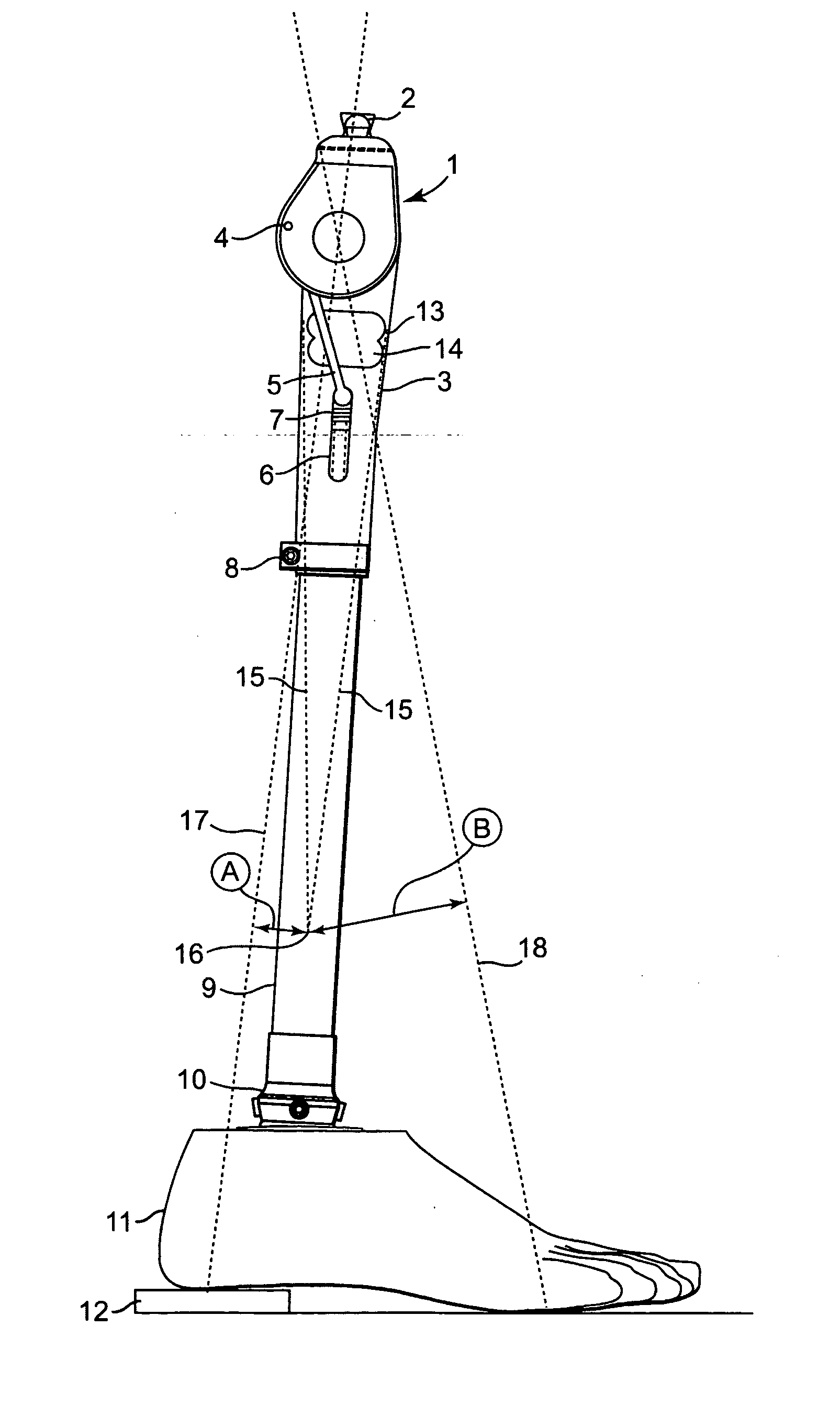
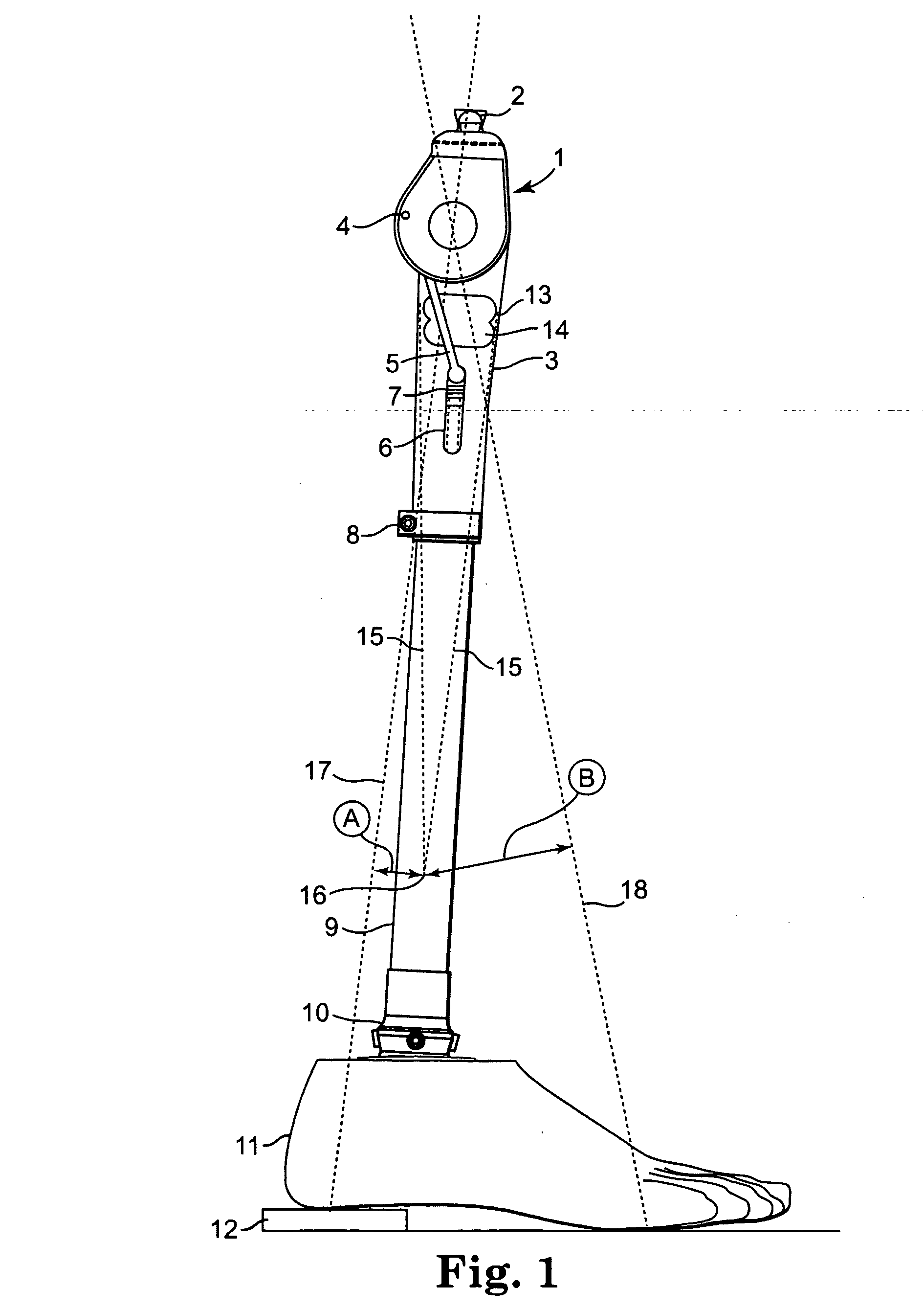
[0023] The prosthesis shown in FIG. 1 has a mono-axial knee joint 1 which can be connected via an adapter 2 to a thigh prosthesis part (not shown). The knee joint 1 has, on its underside, a tube attachment 3 in which a rod 5 connected to an eccentric pivot pin 4 is mounted displaceably in a longitudinal guide 6 counter to the restoring force of a compression spring 7. Upon a flexion movement of the knee joint 1, the rod 5 is pushed downward counter to the force of the restoring spring 7 until the articulation of the auxiliary pin 4 overcomes a lower dead center. The restoring force of the compression spring 7 then supports the further flexion and stabilizes the knee in the flexed position when, for example, the prosthesis user has sat down.

[0024] The knee joint 1 is joined via a connecting sleeve 8 to a below-knee tube 9, the other end of which is connected to an adjustment collar 10 with adjustment pin of an artificial hingeless foot 11. To illustrate the position of use of the ar...


PUM


Abstract

A torque sensor for measuring a torque at a predetermined location of a structural element, in particular of a prosthesis, can be arranged outside the measurement location by virtue of the fact that it is constructed as a sensor structure (13, 13′, 23) that forms a virtual pivot axis (16, 16′) outside the sensor. The sensor structure is provided with measurement transducers (29) which detect deformations of the sensor structure (13, 13′, 23) and are used to determine a torque about the virtual pivot axis (16, 16′). A preferred application for the torque sensor is its incorporation in a prosthesis for the purpose of controlling an artificial joint.

Description

[0001] This patent application claims priority to and the benefit of Germany patent application number 10 2004 004 678.6, filed on Jan. 29, 2004, and entitled DREHMOMENTSENSOR. TECHNICAL FIELD [0002] The invention relates to a torque sensor for measuring a torque at a pre-determined location of a structural element, in particular of a prosthesis. BACKGROUND OF THE INVENTION [0003] The invention is thus concerned with measuring a torque at a defined location of a structural element in order either simply to obtain information about the torque occurring at said location and use this information for warning purposes, or to carry out controls using the information concerning the torque that occurs. It is known in principle to determine torque using suitable measuring elements, for example strain gages, which are applied at the sites where the torque occurs. In many cases, arranging a torque sensor at the measurement site entails considerable design disadvantages, meaning that less suita...

Claims


Application Information

Patent Timeline
Patent Type & Authority Applications(United States)
IPC IPC(8): A61F2/60A61F2/64A61F2/66A61F2/68A61F2/76
CPCA61F2/64A61F2/68A61F2002/7635A61F2002/6614A61F2/76
Inventor BOITEN, HERMAN
Owner OTTOBOCK SE & CO KGAA
Why Eureka
Try Eureka