Lens driving device

a driving device and lens technology, applied in the direction of exposure control, printers, camera focusing arrangement, etc., can solve the problems of large power consumption, inapplicability, mounting a lens driving device equipped with a motor,

Inactive Publication Date: 2004-07-08
SANKYO SEIKI MFG CO LTD
View PDF0 Cites 50 Cited by
  • Summary
  • Abstract
  • Description
  • Claims
  • Application Information

AI Technical Summary

Problems solved by technology

However, it would not be practical, from a size point of view, to mount a lens driving device equipped with a motor on equipment such as cellular phones with camera.
For this reason, the lens driving device of the former type has a problem, namely, it consumes a large amount of power, and therefore is not suitable for mounting on cellular phones with camera.
However, the lens driving device of the latter type has a complex structure and includes a large number of components, and therefore is not suitable for mounting on cellular phones with camera.

Method used


Image

  • Lens driving device
  • Lens driving device
  • Lens driving device

Examples


Embodiment Construction

[0020] A lens driving device in accordance with an embodiment of the present invention will be described below with reference to the accompanying drawings.

[0021] [Overall Structure]

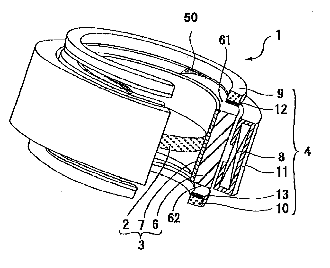
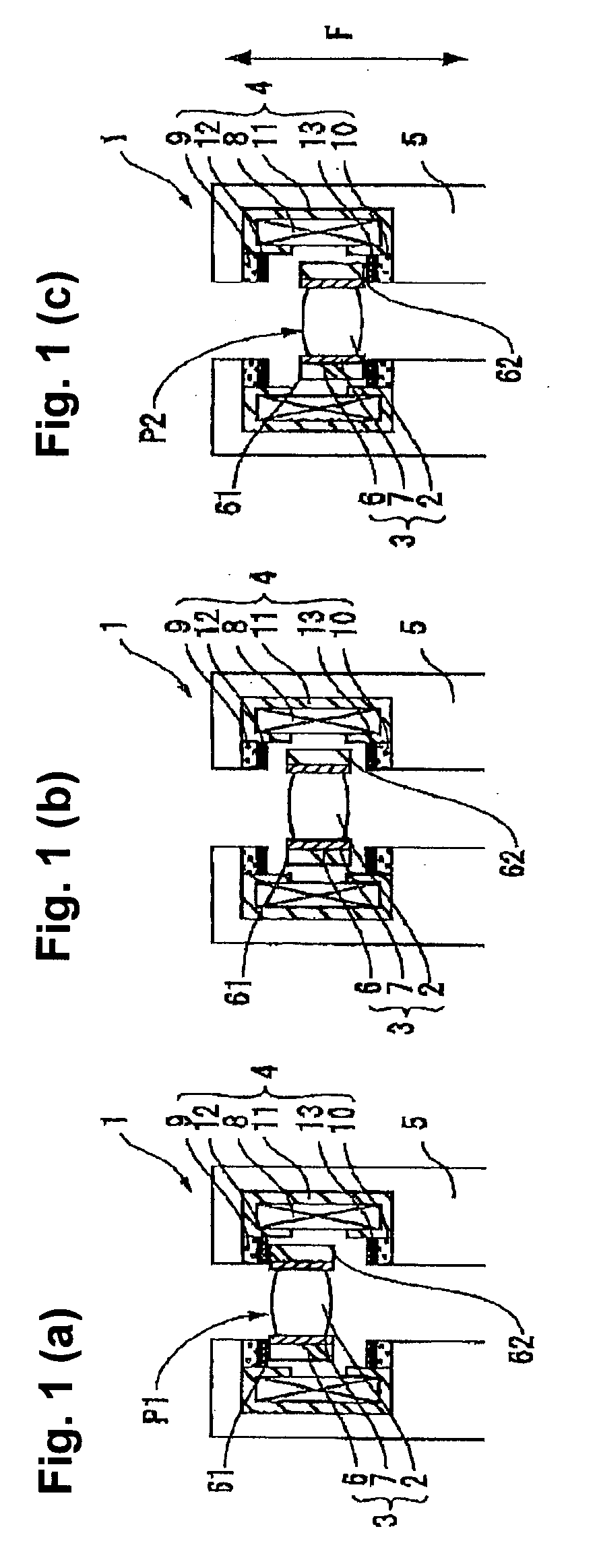
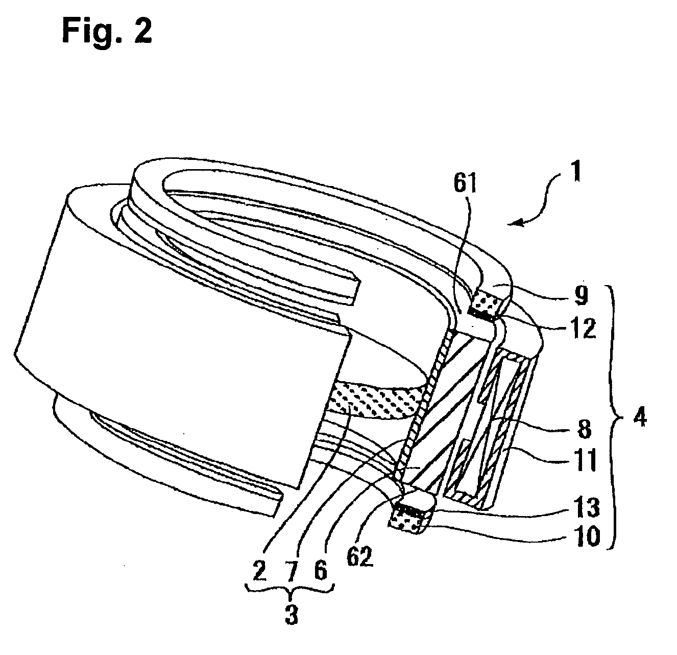
[0022] FIGS. 1(a), 1(b) and 1(c) schematically show cross-sectional views of a lens driving device in accordance with an embodiment of the present invention in a state in which a lens is retained at a first lens retaining position, a state in which the lens is in the course of moving from the first lens retaining position to a second lens retaining position, and a state in which the lens is retained at the second lens retaining position, respectively. FIG. 2 shows an enlarged perspective view of parts of the lens driving device shown in FIGS. 1(a), 1(b) and 1(c).

[0023] As indicated in FIGS. 1(a), 1(b) and 1(c) and FIG. 2, the lens driving device 1 may be used to drive a lens 2 in a thin camera that is mounted on a portable device such as a cellular phone with camera. The lens driving device 1 is generally...


PUM


Abstract

A lens driving device includes a moving body equipped with a lens and a driving magnet attached to the lens, and a fixed body that is equipped with a driving coil that forms together with the driving magnet a magnetic circuit and moves the moving body in an optical axis direction of the lens between a first lens retaining position and a second lens retaining position, and at least one magnetic member disposed adjacent to at least one of two end sections in the optical axis direction of the driving magnet. The moving body is retained at the first lens retaining position by magnetic attraction caused by the driving magnet and the magnetic member when energization of the driving coil is stopped. Accordingly, the driving coil does not need to be energized while the lens is retained at the first lens retaining position.

Description

BACKGROUND OF THE INVENTION:[0001] 1. Field of the Invention[0002] The present invention relates to lens driving devices that are generally used for cameras such as cameras mounted on cellular phones. More particularly, the present invention relates to the technology to drive, position and retain a lens or a lens unit in an optical axial direction.[0003] 2. Related Background Art[0004] A camera device that is mounted on a cellular phone (i.e., portable telephone) with camera typically uses a driving system that drives a lens between two positions, an ordinary photographing position where an ordinary photographing takes place, and a close-up photographing position where the lens is positioned slightly closer to subject by a predetermined distance than its position in the ordinary photographing. However, it would not be practical, from a size point of view, to mount a lens driving device equipped with a motor on equipment such as cellular phones with camera. For this reason, lens driv...

Claims


Application Information

Patent Timeline
Patent Type & Authority Applications(United States)
IPC IPC(8): G02B7/04G02B13/00G03B13/34
CPCH02K41/0356G02B13/001G03B13/34
Inventor YONEYAMA, HIDEKAZUFUJITA, YUJIAZUMA, TAKAHIROKUDO, SHINICHITSURUTA, TOSHIFUMI
Owner SANKYO SEIKI MFG CO LTD
Why Eureka
Try Eureka