
Thru tubing tool and method

a technology of expanding anchoring and tubing, which is applied in the direction of drilling pipes, directional drilling, borehole/well accessories, etc., can solve the problems of limited radial expansion capability, limited ability to securely anchor within the larger tubular diameter, and the tendency of conventional thru tubing whipstock supports to be susceptible to small but not insignificant movement, etc., to achieve the effect of supporting loading

Active Publication Date: 2004-08-05
WELLBORE INTEGRITY SOLUTIONS LLC
View PDF11 Cites 11 Cited by
  • Summary
  • Abstract
  • Description
  • Claims
  • Application Information

AI Technical Summary

Benefits of technology

This patent describes an improved way for supporting loads during drilling operations by using an expansible tool that can fit into different types of well bores (both cased and open). The tool has slip elements that make contact with the wall of the well bore to provide stability while it's being worked. Overall, this technology allows for safer and more efficient drilling without having to rely solely on the strength of the rock formations surrounding the well.

Problems solved by technology

The technical problem addressed in this patent is how to safely and efficiently run well tools through a smaller diameter tubular and then set up in a larger diameter casing without causing significant movement of the anchored whipstock.

Method used


Image

  • Thru tubing tool and method
  • Thru tubing tool and method
  • Thru tubing tool and method

Examples


Embodiment Construction

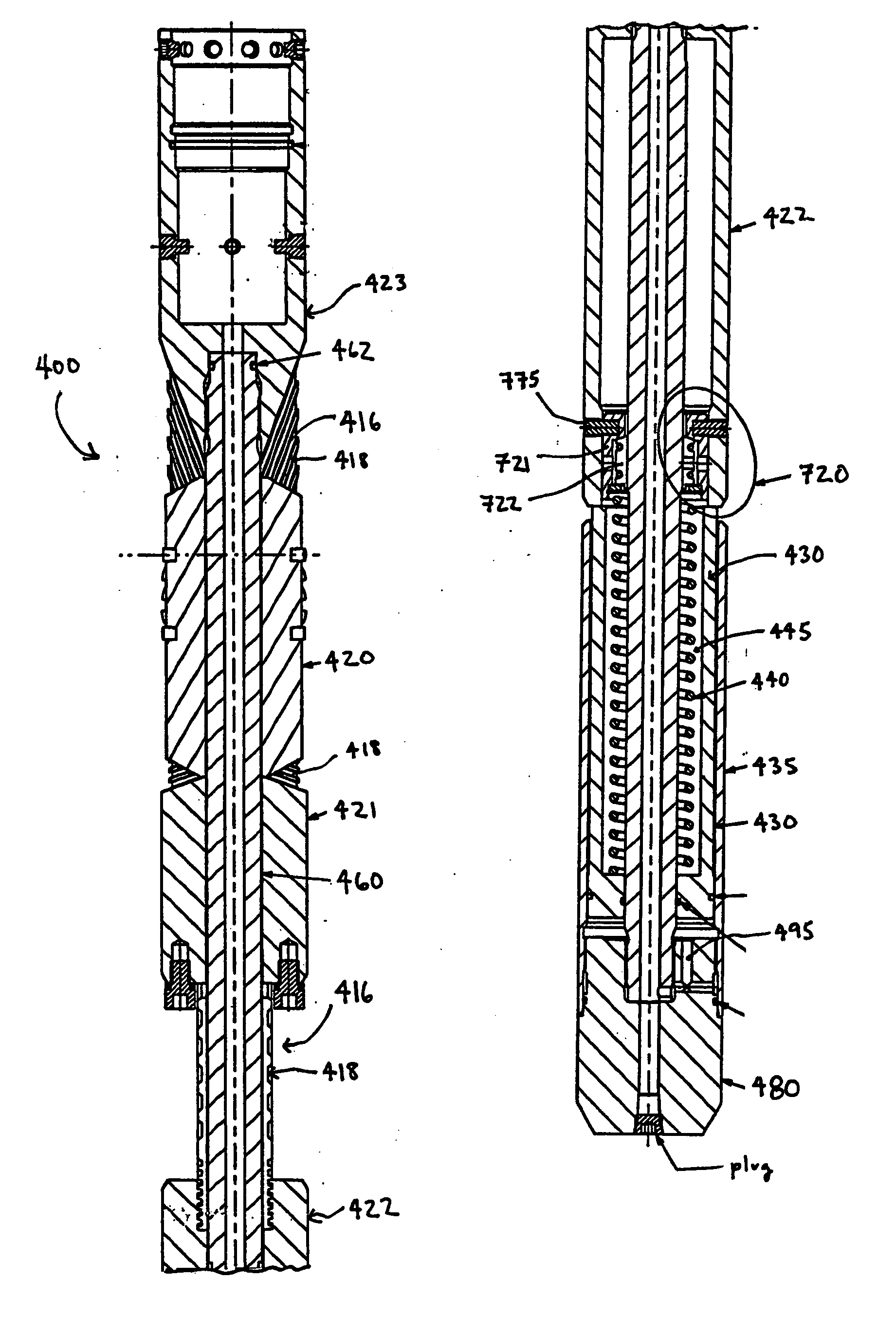
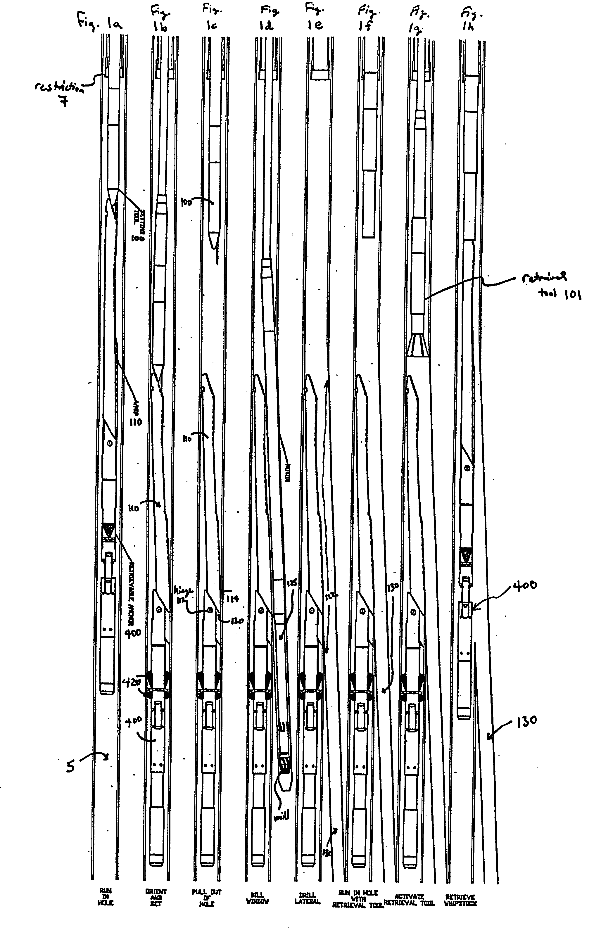
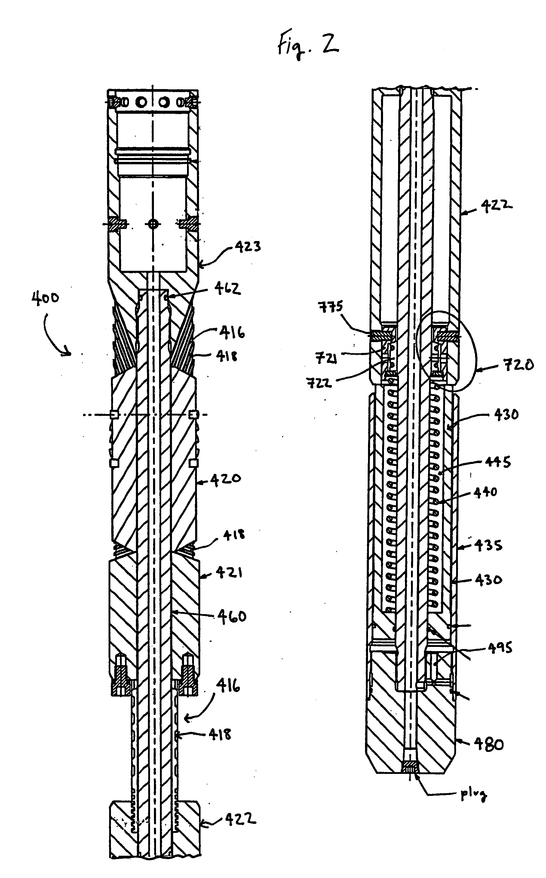
[0011] The preferred embodiments of the present invention feature a downhole expandable anchoring tool that may be used for passing through a restricted wellbore diameter while in a collapsed position and thereafter translating to an expanded position for grippingly engaging a larger wellbore diameter. The use of the expandable anchoring tool of the present invention, however, is not limited to well operations below a restriction, but may be used in any type of wellbore, including but not limited to unrestricted wellbores, cased wellbores, or uncased wellbores.

[0012] An embodiment of the tool includes a body including a plurality of angled channels formed into a wall of the body and a plurality of moveable slips. The plurality of moveable slips translates along the plurality of angled channels between a collapsed position and an expanded position. The slips may include includes a plurality of extensions corresponding to and engaging the plurality of channels.

[0013] In one preferred ...


PUM


Abstract

A downhole tool is disclosed that functions as an expandable anchoring tool, capable of passing through a restricted wellbore diameter while in a collapsed position and thereafter translating to an expanded position for grippingly engaging a larger wellbore diameter. An embodiment of the tool includes a body including a plurality of angled channels formed into a wall of the body and a plurality of moveable slips. The plurality of moveable slips translates along the plurality of angled channels between a collapsed position and an expanded position. The slips may include includes a plurality of extensions corresponding to and engaging the plurality of channels.

Description


Claims


Application Information

Patent Timeline
Owner WELLBORE INTEGRITY SOLUTIONS LLC
Learn More