Interlocking screens for vibratory separators

a technology of interlocking screens and separators, which is applied in the direction of filtration separation, separation processes, moving filter elements, etc., can solve the problems of difficult removal of these screen assemblies, and achieve the effect of improving the sealing

a technology of interlocking screens and separators, which is applied in the direction of filtration separation, separation processes, moving filter elements, etc., can solve the problems of difficult removal of these screen assemblies, and achieve the effect of improving the sealing

US20040149632A1Inactive Publication Date: 2004-08-05VARCO I P INC

Image

  • Interlocking screens for vibratory separators
  • Interlocking screens for vibratory separators
  • Interlocking screens for vibratory separators

Examples


Embodiment Construction

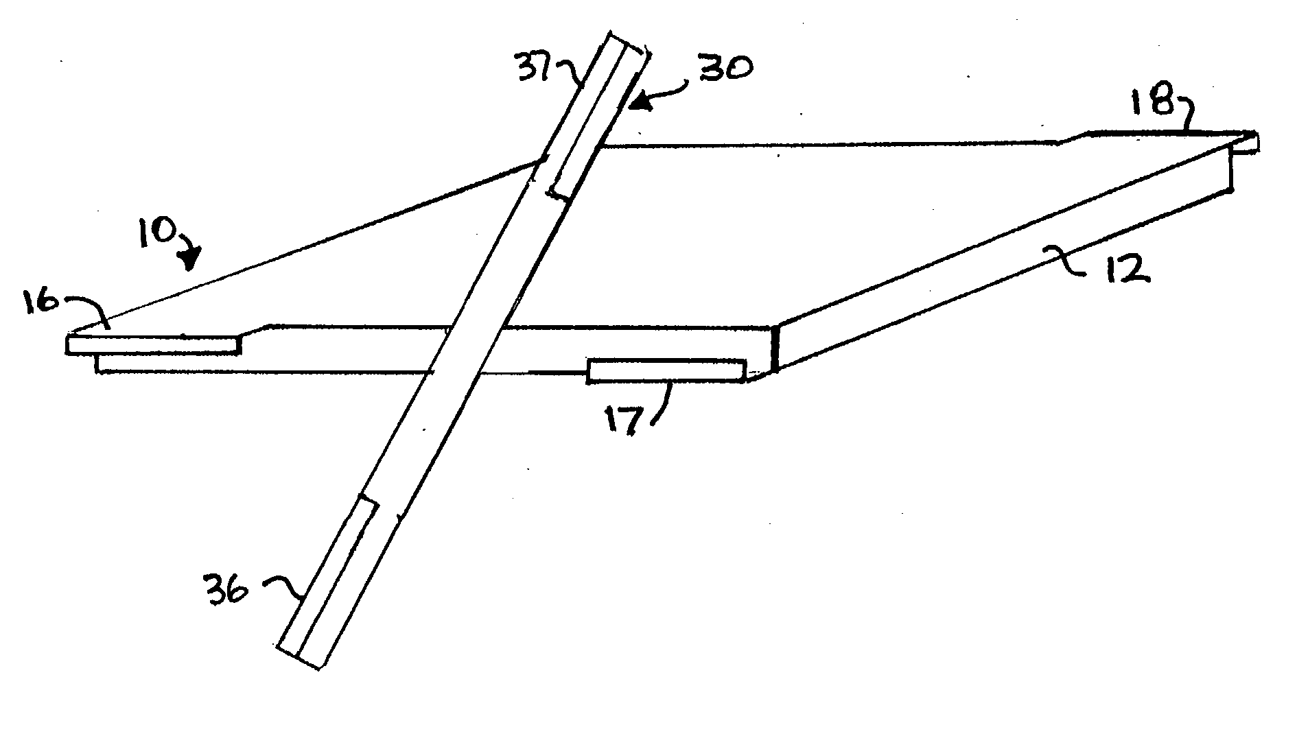
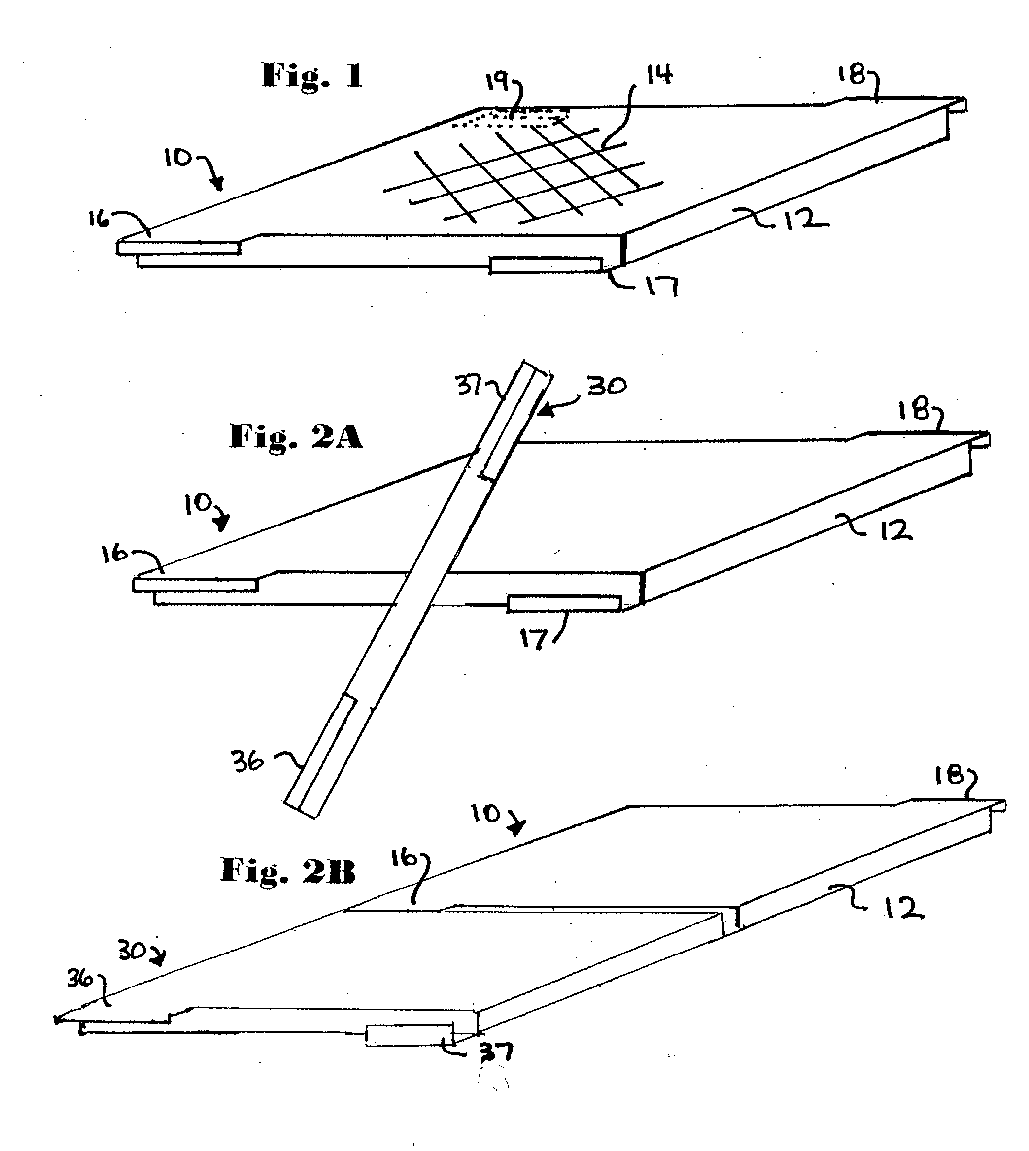
[0033] FIG. 1 shows schematically a screen assembly 10 according to the present invention for a vibratory separator or shale shaker which has a support or frame 12 with screening material 14. It is to be understood that it is within the scope of the present invention for side and / or cross members of the support or frame 12 to be like any such known support or frame members, including but not limited to, those of supports and frames in U.S. Pat. Nos. 5,417,793; 5,417,859; 5,417,858; 6,443,310; 6,439,392 and in the prior art cited therein. According to the present invention end members 16, 17, 18 and 19 of the frame 12 have lips 21 and 22 projecting therefrom. Each lip has a vertical portion (portions 16a, 17a and 18a shows in FIG. 1) connected to a horizontal portion (portions 16b, 17b, and 18b shown in FIG. 1). Such portions can be added to, secured to or formed integrally of any suitable known support or frame member to effect a frame or support according to the present invention. ...


PUM

PropertyMeasurementUnit
lengthaaaaaaaaaa
lengthsaaaaaaaaaa
timeaaaaaaaaaa

Abstract

Interconnectible screen assemblies for vibratory separators or shale shakers and methods for manipulating such screen assemblies which, in certain aspects, include a first screen assembly and a second screen assembly positioning at least a portion of the first screen assembly with respect to screen assembly holding apparatus, connecting a second screen assembly to the first screen assembly, and moving the first screen assembly and the second screen assembly together with respect to the screen assembly holding apparatus.

Description

[0001] 1. Field of the Invention[0002] The present invention is directed to screen assemblies for vibratory separators and shale shakers and to methods of mounting them within and removing them from such separators and shakers.[0003] 2. Description of Related Art[0004] The prior art discloses a variety of screen assembly mounting structures for holding screen assemblies in position. In many instances screen assemblies are positioned sequentially on or within mounting structures of a vibratory separator or shale shaker. For example, many such apparatuses have spaced apart channels into which screen assemblies are inserted one after the other and from which they are removed sequentially one at a time. Often removal of these screen assemblies can be difficult, particularly the removal of those farthest away from an insertion end of the mounting structure or fluid exit end of a support deck.[0005] There has long been a need, recognized by the present inventors, for screen assemblies tha...

Claims


Application Information

Patent Timeline
05 Aug 2004
Publication
US20040149632A1
IPC
B01D33/03; B07B1/46
CPC
B01D33/0376; B01D2201/4084; B07B1/4645; B07B1/4663; B07B2201/02; B07B1/469; B01D33/37
Inventors
SCHULTE, DAVID L. JR.; MCCLUNG, GUY L. III