Alignment method of the optical transmitter and receiver in the optical wireless communication system

Inactive Publication Date: 2004-08-05
INST FOR INFORMATION TECH ADVANCEMENT +1
View PDF5 Cites 6 Cited by
  • Summary
  • Abstract
  • Description
  • Claims
  • Application Information

AI Technical Summary

Problems solved by technology

However, if one observes the laser light with the infrared ray viewer for a long time, his eyes become to be fatigued.
Moreover, one has difficulty in observing wide region, because observation region is limited to a moving distance of his eyes.
Moreover, alignment speed is slow, and corresponding the center of the laser light to the light reception unit of the receiver exactly is difficult, because the transmitter cannot align itself without the indication of the receiver.
In case of the screw, manufacture is difficult, and a unit cost of manufacture becomes to be high because the detailed degree of screw line has to be very high.
Moreover, in case of the motor, not only

Method used


Image

  • Alignment method of the optical transmitter and receiver in the optical wireless communication system
  • Alignment method of the optical transmitter and receiver in the optical wireless communication system
  • Alignment method of the optical transmitter and receiver in the optical wireless communication system

Examples


Embodiment Construction

[0039] With referring to the drawings, preferred embodiments of the present invention will be described in the following.

[0040] The alignment method for aligning an optical transmitter and receiver according to the present invention can be widely classified to a) a manual alignment method, b) an automatic alignment method, c) a mixed alignment method of the manual and automatic alignment methods. The main characteristic of these alignment methods is that the transmitter can be aligned directly with confirming a position of the laser light arrived in the receiver without an indication of the receiver side.

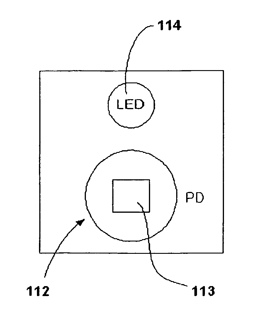
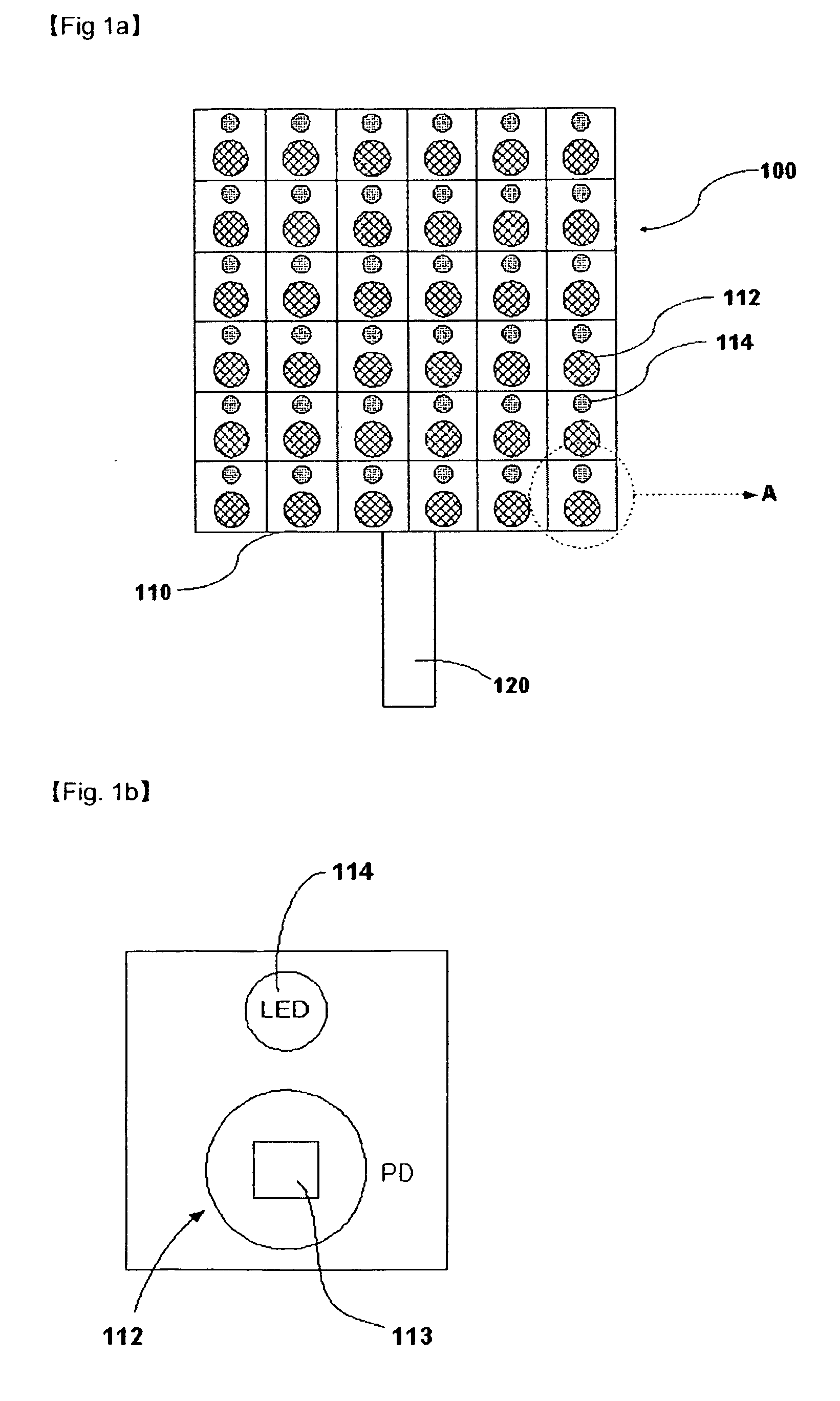
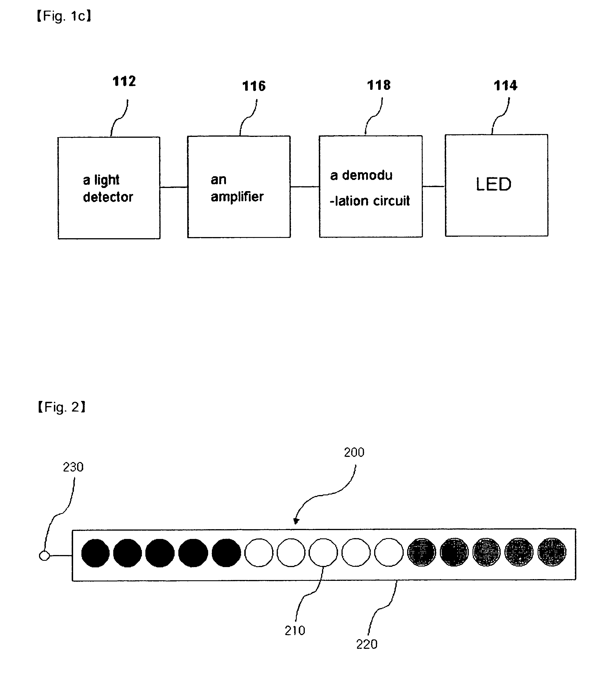
[0041] In the present invention, an infrared ray detection board comprising a light detector and a LED, and a LED indicator is proposed as equipment for observing the position of the laser light.

[0042] First, construction and function of the infrared ray detection board are illustrated. FIG. 1a.about.FIG. 1c shows a construction of the infrared ray detection board. FIG. 1a shows an ...


PUM


Abstract

Infrared ray detecting board which is able to observe the intensity, size and shape of the laser light from the transmitter and to separate the laser light of the transmitter from the external infrared rays to confirm the arriving position of the laser light to the receiver at the transmitter side directly, and LED indicator for corresponding the center of the laser light to the photo-detecting region of the receiver are provided. Moreover, various alignment methods using such devices and an alignment device having removable motor are provided.

Description

[0001] The present invention relates to an apparatus and method for aligning a transmitter and receiver in the optical wireless communication system, more particularly, to an apparatus for observing an arrived position of a laser light to the receiver directly at the transmitter side, an alignment method for aligning the transmitter and receiver using thereof, and an aligner.RELATED ART[0002] A process of aligning a transmitter and receiver is required to construct the optical wireless communication system so that the receiver can exactly receive a laser light from the transmitter. A prior alignment method that has been used in the optical wireless communication system has below steps.[0003] a) Setting equipments temporarily to be opposite each other with a telescope or a sight telescope.[0004] b) Observing an arrived position of a laser light from the transmitter at the receiver side with IR viewer.[0005] c) Moving the transmitter with a screw or a motor until the laser light from ...

Claims


Application Information

Patent Timeline
IPC IPC(8): H04B10/112
CPCH04B10/1127
Inventor CHO, KYUMANCHOI, YOUNGWANJEONG, HEESEONG
Owner INST FOR INFORMATION TECH ADVANCEMENT
Why Eureka
Try Eureka