Adjustable rear suspension for a tracked vehicle

a rear suspension and track suspension technology, applied in the direction of hand cart accessories, rider propulsion, hand carts, etc., can solve the problems of large force on the block, difficulty in rotating the adjuster block or removing it for maintenance and cleaning, and obvious drawbacks, etc., to achieve the effect of small shearing for

Inactive Publication Date: 2001-03-27
BOMBARDIER RECREATIONAL PROD INC
View PDF16 Cites 62 Cited by
  • Summary
  • Abstract
  • Description
  • Claims
  • Application Information

AI Technical Summary

Benefits of technology

FIG. 11 is a schematic view showing that, in the present invention, the blocks are located at a greater distance from the ...

Problems solved by technology

However, certain drawbacks are evident from the Peppel et al. design.
These drawbacks result from the direct mounting of the adjuster blocks to the slide frame.
Firstly, since the adjuster blocks are mounted on the inside of the slide frame in close proximity to the rear suspension arm, it is awkward to rotate the adjuster blocks or to remove them for maintenance and cleaning.
Secondly, the adjuster blocks are offset with respect to the rails.
When the snowmobile encounters bumps, very large forces are exerted on the blocks.
This results in relatively large loads bei...

Method used


Image

  • Adjustable rear suspension for a tracked vehicle
  • Adjustable rear suspension for a tracked vehicle
  • Adjustable rear suspension for a tracked vehicle

Examples


Embodiment Construction

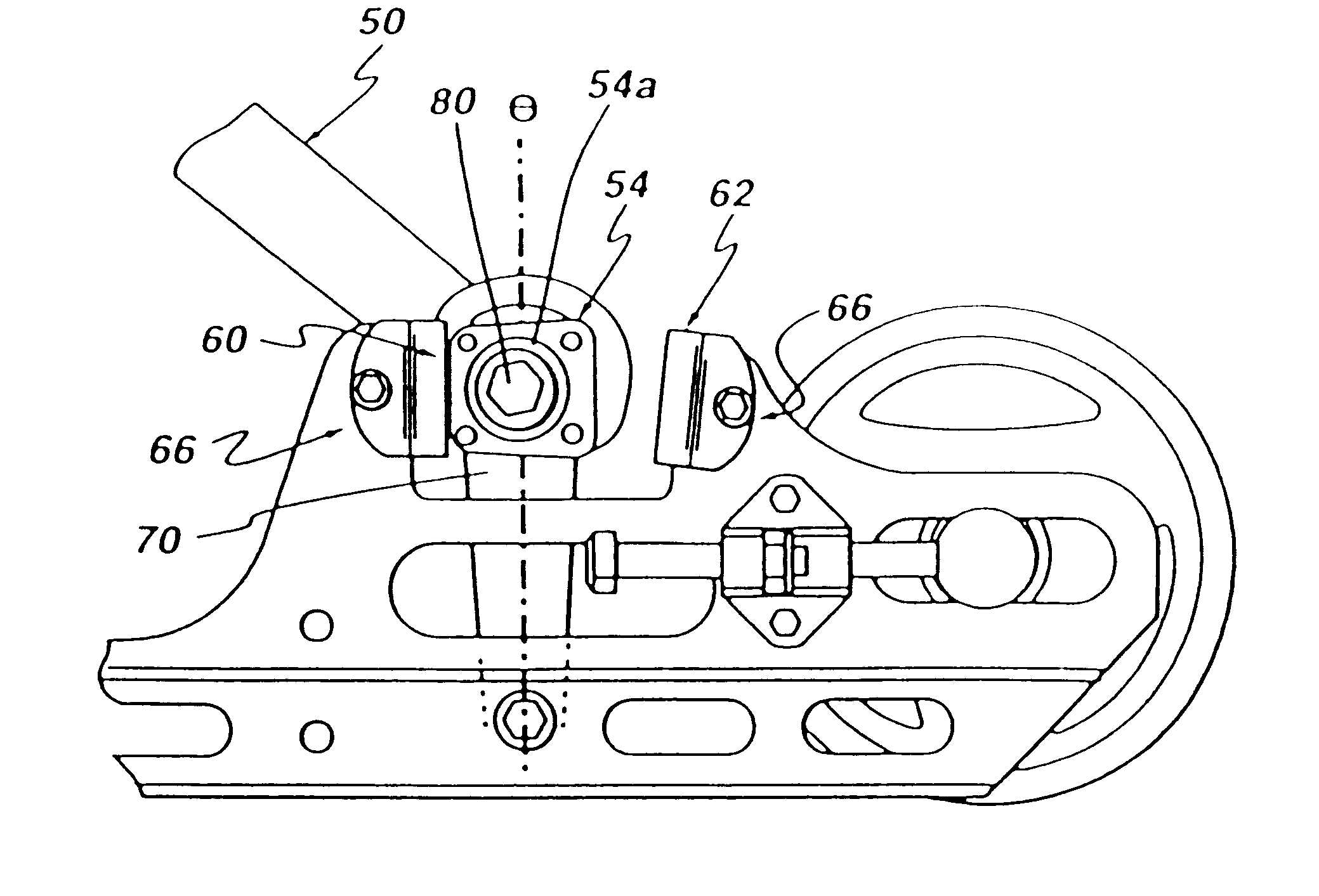
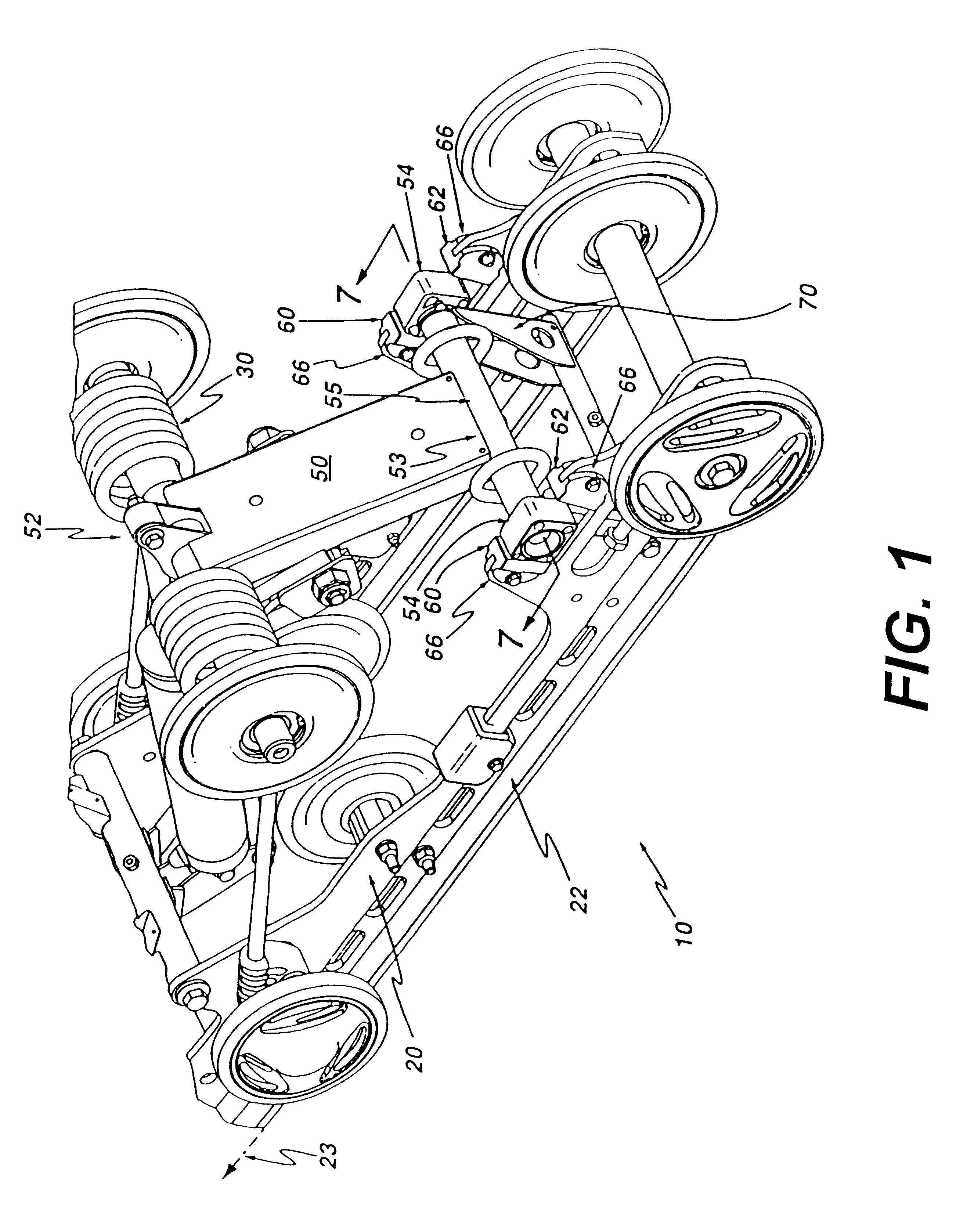
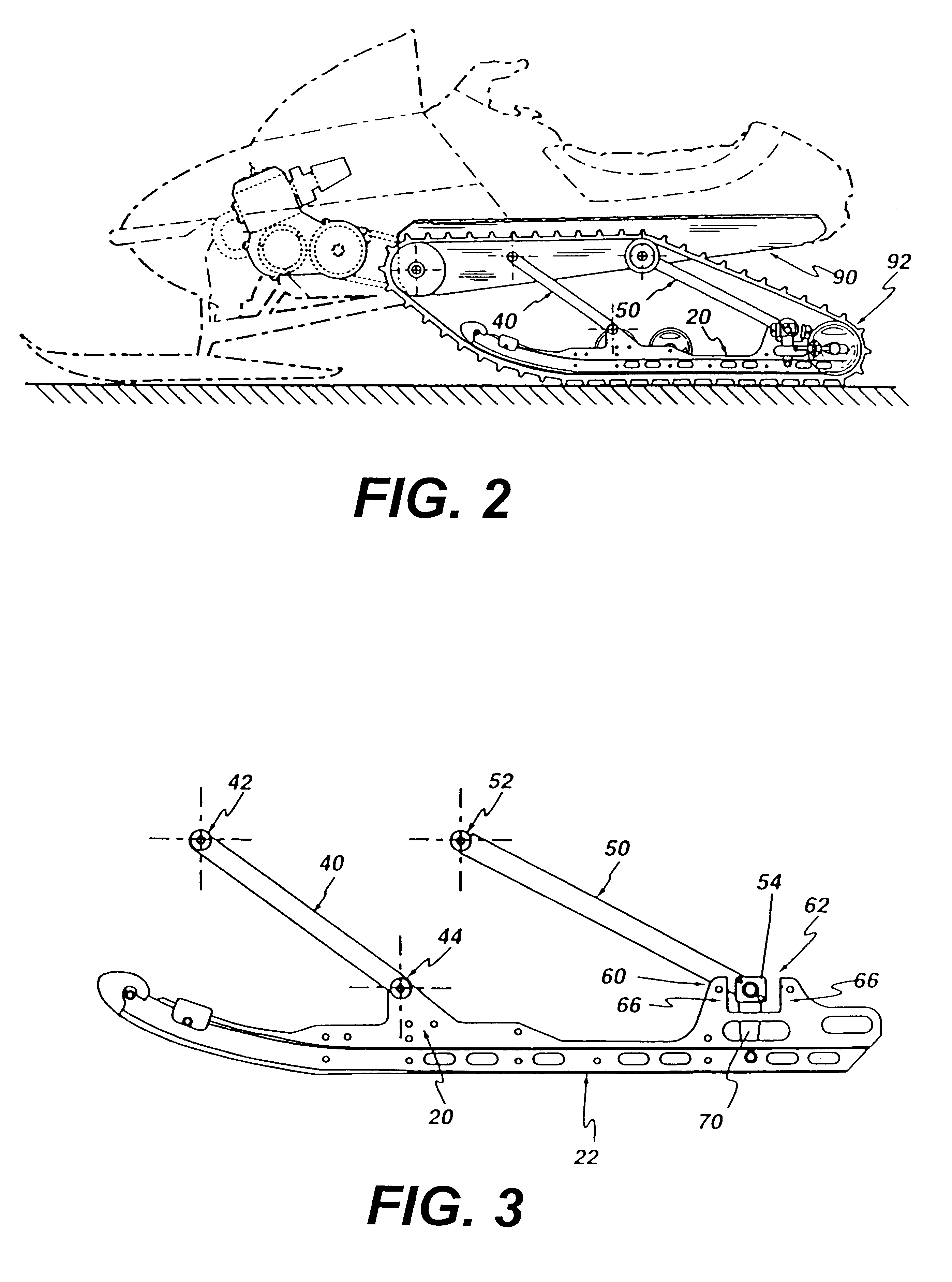
Referring to FIGS. 1, 2 and 3, an adjustable rear suspension system, designated comprehensively by the reference numeral 10, is used for mounting an endless track 92 to a chassis 90. The suspension system 10 comprises a slide frame 20, a front suspension arm assembly 40 and a rear suspension arm assembly 50. The slide frame 20 comprises a pair of parallel slide rails 22 which are maintained at a spaced apart relationship by at least one cross-brace, the slide rails defining a longitudinal direction 23. Also mounted to the slide frame are a plurality of wheels for engagement with the endless track 92. At least one spring-like member 30 is connected to the chassis 90 and the slide frame 20 so as to urge the slide frame 20 downwardly away from the chassis. The spring-like member 30 is preferably a linear, non-linear or torsional metallic spring and is advantageously coupled with a damper or shock absorber to attenuate vibrations.

The front suspension arm assembly 40 has an upper end 42 ...


PUM


Abstract

An adjustable rear suspension system for a tracked vehicle comprises a slide frame for guiding a portion of the endless track, the slide frame having a pair of substantially parallel slide rails, the slide rails defining a longitudinal direction. The rear suspension system further comprises at least one spring-like member for urging the slide frame away from the chassis. A front suspension arm assembly has an upper end pivotally connected to the chassis and a lower end pivotally connected to the slide frame. A rear suspension arm assembly has ail upper arm pivotally connected to the chassis and a lower end connected to at least one block capable of limited displacement in the longitudinal direction between a front stopper and a rear stopper. The rear suspension system further includes a rocker arm having an upper end connected to at least one block and a lower end pivotally connected to the slide frame. This rear suspension system compensates for rearward weight transfer caused by rapid forward acceleration of the tracked vehicle.

Description

This invention relates to suspension systems for tracked vehicles, and, more specifically, to rear suspension systems for snowmobiles.The dynamic response of a rear suspension system to the multitude of loads imposed upon it during operation is undoubtedly one of the most critical factors in determining the overall performance and ride comfort of a tracked vehicle such as a snowmobile. A rear suspension system generally has to contend with three types of loads that are regularly exerted upon a tracked vehicle regardless of whether it is employed for racing or mere recreation. First and foremost in severity are the impact loads imposed upon the rear suspension as the vehicle traverses rough terrain and encounters bumps. Secondly, there are internal forces developed during rapid acceleration which cause a weight transfer from the front of the vehicle to the rear. This tends to lift the skis off the ground and thus hampers steering. Finally, there are centrifugal loads imposed on the v...

Claims


Application Information

Patent Timeline
IPC IPC(8): B62D55/104
CPCB62D55/104B62M2027/026
Inventor MALLETTE, BERTRANDLANGLAIS, STEVE
Owner BOMBARDIER RECREATIONAL PROD INC
Why Eureka
Try Eureka