Pneumatic radial tire

a radial tire and pneumatic technology, applied in the direction of tyre tread bands/patterns, vehicle components, vehicle components, etc., can solve the problems of increasing contact patch pressure, lateral force producing localized wear reducing the abrasive energy at the end of the main lug portion of the shoulder lug, so as to delay the occurrence of wear and reduce the shear force and slippage in the tire width

Active Publication Date: 2019-06-27
TOYO TIRE & RUBBER CO LTD
View PDF0 Cites 2 Cited by
  • Summary
  • Abstract
  • Description
  • Claims
  • Application Information

AI Technical Summary

Benefits of technology

[0010]Because low-modulus rubber, for which the stress at a given elongation is lower than that of cap rubber, is thus arranged at the corner of main lug portion, contact patch pressure at the end of main lug portion is alleviated, shear force and slippage in the tire width direction are made small, abrasive energy at the end of main lug portion is reduced, and it is possible to delay occurrence of wear at the end of main lug portion. It is therefore possible to suppress occurrence of uneven wear.

Problems solved by technology

With pneumatic tires intended for heavy loads such as may be employed in trucks, buses, and so forth, a type of uneven wear is known in which there is a general tendency for compression within the contact patch that is produced during contact with the ground to cause contact patch pressure to increase in the vicinity of the edges of the contact patch at shoulder lugs, as a result of which the amount of wear in the vicinity of the edges of the contact patch at shoulder lugs is greater than at other lugs within the contact patch.
However, with tires intended for highways where it is envisioned that one will be driving straight ahead such as is primarily the case when driving on highways in the United States and so forth, compression within the contact patch that is produced during contact with the ground can cause a lateral force to act that is directed from the exterior to the interior in the tire width direction.
This lateral force produces localized wear at the end of the main lug portion of the shoulder lug.
In particular, the end of the main lug portion is such that, contact patch pressure being high as compared with a central region in the tire width direction of the shoulder lug, the lateral force due to compression within the contact patch during contact with the ground is large, and slippage in the lateral direction produces an increase in abrasive energy in the tire width direction.

Method used


Image

  • Pneumatic radial tire
  • Pneumatic radial tire
  • Pneumatic radial tire

Examples


Embodiment Construction

[0019]Below, a pneumatic radial tire in an embodiment in accordance with the present disclosure is described with reference to the drawings.

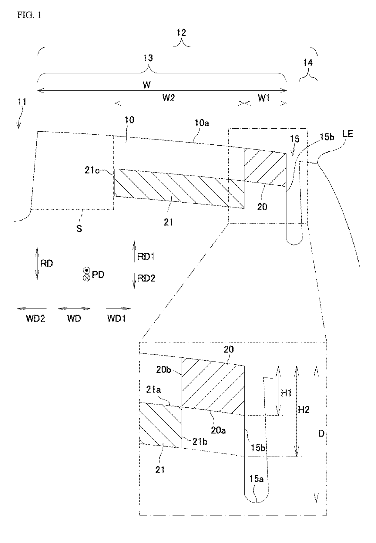
[0020]FIG. 1 is an exemplary sectional view taken along the tire meridional direction at a shoulder lug in a pneumatic radial tire in accordance with the present invention. As shown in FIG. 1, a pneumatic radial tire associated with the present embodiment has cap rubber 10 which forms the contact patch. Cap rubber 10 has a plurality of major grooves 11 extending in the tire circumferential direction PD, and a plurality of lugs that extend in the tire circumferential direction PD and that are partitioned by the plurality of major grooves 11. FIG. 1 shows shoulder lug 12 which is outwardmost in the tire width direction WD.

[0021]As shown in FIG. 1, shoulder lug 12 has narrow groove 15 that extends in the tire circumferential direction. Narrow groove 15 partitions shoulder lug 12 into main lug portion 13 toward the interior WD2 in the tire width dir...


PUM

PropertyMeasurementUnit
sizeaaaaaaaaaa
groove widthaaaaaaaaaa
widthaaaaaaaaaa

Abstract

A tire has cap rubber that forms a contact patch. The cap rubber has a plurality of lugs. A shoulder lug, which among the plurality of lugs is that which is located outwardmost in a tire width direction, has a narrow groove that extends in the tire circumferential direction and that partitions the shoulder lug into a main lug portion toward the interior in the tire width direction, and a sacrificial lug portion toward the exterior in the tire width direction; and low-modulus rubber, for which stress at a given elongation is lower than that of the cap rubber, is arranged at a corner where the contact patch at the main lug portion and a groove side face toward the interior in the tire width direction which forms the narrow groove intersect.

Description

BACKGROUND OF THE INVENTIONField of the Invention[0001]The present disclosure relates to a pneumatic radial tire intended for heavy loads.Description of the Related Art[0002]With pneumatic tires intended for heavy loads such as may be employed in trucks, buses, and so forth, a type of uneven wear is known in which there is a general tendency for compression within the contact patch that is produced during contact with the ground to cause contact patch pressure to increase in the vicinity of the edges of the contact patch at shoulder lugs, as a result of which the amount of wear in the vicinity of the edges of the contact patch at shoulder lugs is greater than at other lugs within the contact patch. Widely carried out to suppress such uneven wear is a method in which narrow groove(s) that extend in the tire circumferential direction and that partition the shoulder lug into main lug portion(s), and into sacrificial lug portion(s) toward the exterior in the tire width direction therefr...

Claims


Application Information

Patent Timeline
Patent Type & Authority Applications(United States)
IPC IPC(8): B60C9/20
CPCB60C9/20B60C2009/0078B60C2009/2064B60C11/00B60C11/01B60C2011/0016B60C2011/013B60C11/0311B60C11/0058B60C2011/0025B60C2011/0348B60C11/005B60C11/12B60C2011/0393B60C2011/0397
Inventor SUITA, HARUNOBU
Owner TOYO TIRE & RUBBER CO LTD
Why Eureka
Try Eureka