Method of manufacturing color filters

a technology of color filters and manufacturing methods, applied in the field of color filter manufacturing methods, can solve the problems of uneven support, difficult to avoid and the tendency of support damage caused by over-etching treatment, and achieve the effect of preventing the occurrence of support damag

Inactive Publication Date: 2009-05-26
FUJIFILM CORP
View PDF20 Cites 1 Cited by
  • Summary
  • Abstract
  • Description
  • Claims
  • Application Information

AI Technical Summary

Benefits of technology

[0018]In this dry etching, the stopper layer is etched only slightly because the etching rate of the stopper layer by the second mixed gas is low, and therefore, damage is not caused to the substrate, which is located under the stopper layer. Thus, a color filter with its support free from damage and having good rectangularity is fabricated.
[0020]As described so far, the present invention provides a color filter manufacturing method which is capable of retarding the occurrence of support damage during dry etching treatment.

Problems solved by technology

In manufacturing of color filters using dry etching process, usually the problem of support damage (shaving) caused by over-etching treatment tends to occur.
For example, when intending to form a pattern by removing the colored layer on a support by dry etching, part of the support in the area where the colored layer has been removed is sometimes shaved, thereby causing unevenness on the support.
Or, over-etching treatment is sometimes carried out after detecting the end point of etching to remove residues on a support, in that case, when an organic film exists on the support or etching gas containing fluorine-based gas is used, it is difficult to avoid the occurrence of support damage.

Method used


Image

  • Method of manufacturing color filters
  • Method of manufacturing color filters
  • Method of manufacturing color filters

Examples


examples

[0146]In the following the present invention will be described in detail by examples; however, it is to be understood that the invention is not limited to these examples.

[0147]When using a commercial treatment solution to carry out treatment in each of the steps described below, unless otherwise specified, each treatment was carried out in accordance with the method designated by the manufacturer

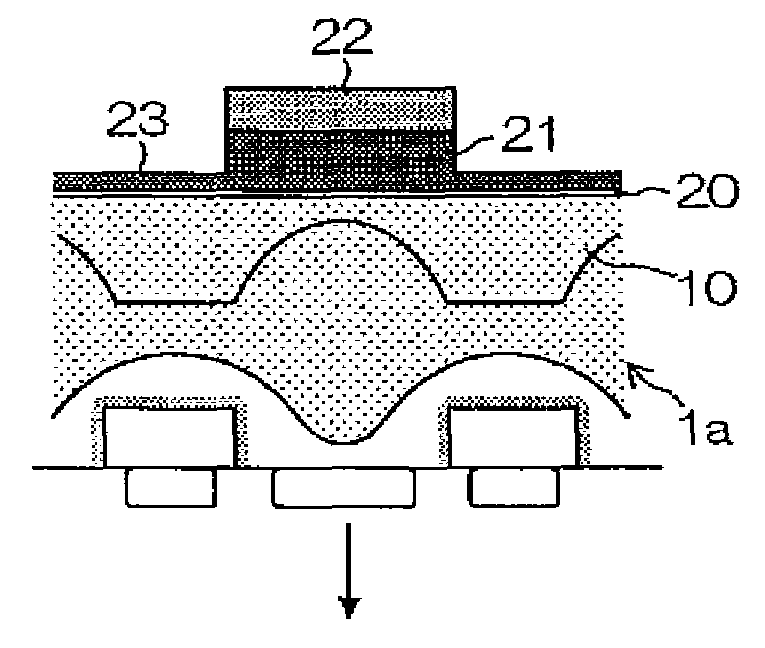
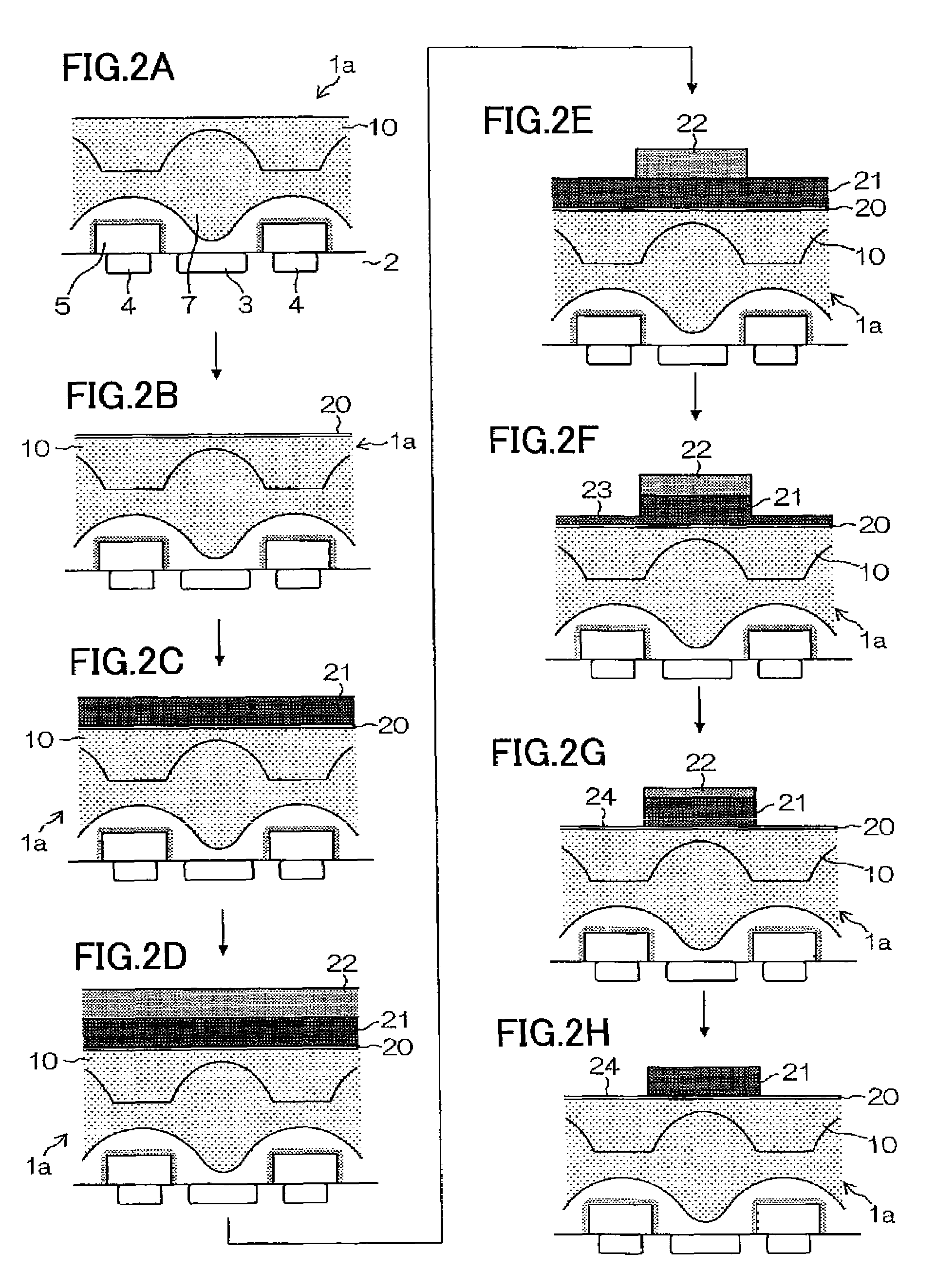
[0148]In the support forming step in examples, the plarnarized layer 10, as shown in FIGS. 2A to 2H, was formed on a silicon wafer. First a silicon wafer was coated with a negative-type plarnarized layer, CT-4000L, manufactured by FUJIFILM Electronic Materials Co., Ltd., using a spin coater (Mark 8, manufactured by Tokyo Electron Ltd.), then subjected to flood exposure at an exposure dose of 200 mJ / cm2 using an i-ray stepper (FPA3000i5+, manufactured by Canon Inc.), followed by 5-minute heating at 220° C. using a hot plate to form a planarized layer having a thickness of 0.1 μm.

[0149]In the ...


PUM

PropertyMeasurementUnit
thicknessaaaaaaaaaa
temperatureaaaaaaaaaa
sizeaaaaaaaaaa

Abstract

The present invention provides a method of manufacturing color filters using a first mixed gas and a second mixed gas. In the method, a stopper layer whose etching rate by the second mixed gas is low is formed on the support, a colored layer is formed on the stopper layer, a photo resist layer is formed on the colored layer, an image on the colored layer is formed by removing the photo resist layer according to a pattern, a part of the colored layer is removed by dry etching process using the first mixed gas to the extent that the stopper layer is not exposed removing so as to form a colored-layer removed portion according to the pattern, and the colored-layer removed portion is removed by dry etching process using the second mixed gas so as to form a stopper-layer exposed portion according to the pattern.

Description

BACKGROUND OF THE INVENTION[0001]1. Field of the Invention[0002]The present invention relates to a color filter manufacturing method using dry etching process.[0003]2. Description of the Related Art[0004]Dyeing, printing, electrodeposition and pigment dispersion methods have been known as methods for fabricating color filters for use in liquid crystal display devices or solid-state image sensors.[0005]Of these methods, pigment dispersion method is to fabricate color filters by photolithography process using a radiation sensitive colored composition which is prepared by dispersing a pigment in one of various types of photosensitive compositions. This method offers the advantage of having good stability to light and heat because it uses a pigment. Furthermore, the method ensures high positioning accuracy because it employs photolithography process for patterning; therefore, it has been widely used as a suitable method for fabricating color filters for use in large-size and high-defini...

Claims


Application Information

Patent Timeline
Patent Type & Authority Patents(United States)
IPC IPC(8): G02B5/20
CPCG02B5/201H01L27/14621H01L27/14685G02F1/133516
Inventor SUZUKI, HISASHI
Owner FUJIFILM CORP
Why Eureka
Try Eureka