
Rear-earth magnet and its producing method

A technology of rare earth magnets and manufacturing methods, applied in the direction of inductance/transformer/magnet manufacturing, magnetic objects, magnetic materials, etc., which can solve the problems of the reduction of residual magnetic flux density of rare earth magnets, the reduction of magnet processing efficiency, and the reduction of cutting and surface grinding processing efficiency and other problems, to achieve the effect of increased coercive force, inhibited particle growth, and good rectangularity

Inactive Publication Date: 2004-12-29
HITACHI METALS LTD
View PDF3 Cites 9 Cited by
  • Summary
  • Abstract
  • Description
  • Claims
  • Application Information

AI Technical Summary

Problems solved by technology

Due to the formation of such non-magnetic borides, the rare earth magnets harden after the sintering process, which greatly reduces the processing efficiency of cutting and surface grinding.
[0006] In addition, in the prior art described in Japanese Patent Publication No. 6-69003, since the amount of metals such as Nb added is large, it is easy to generate NbFeB 2 non-magnetic borides
After the sintering process, the residual magnetic flux density of the rare earth magnet decreases, and the processing efficiency of the magnet also decreases

Method used


Image

  • Rear-earth magnet and its producing method
  • Rear-earth magnet and its producing method
  • Rear-earth magnet and its producing method

Examples


Embodiment Construction

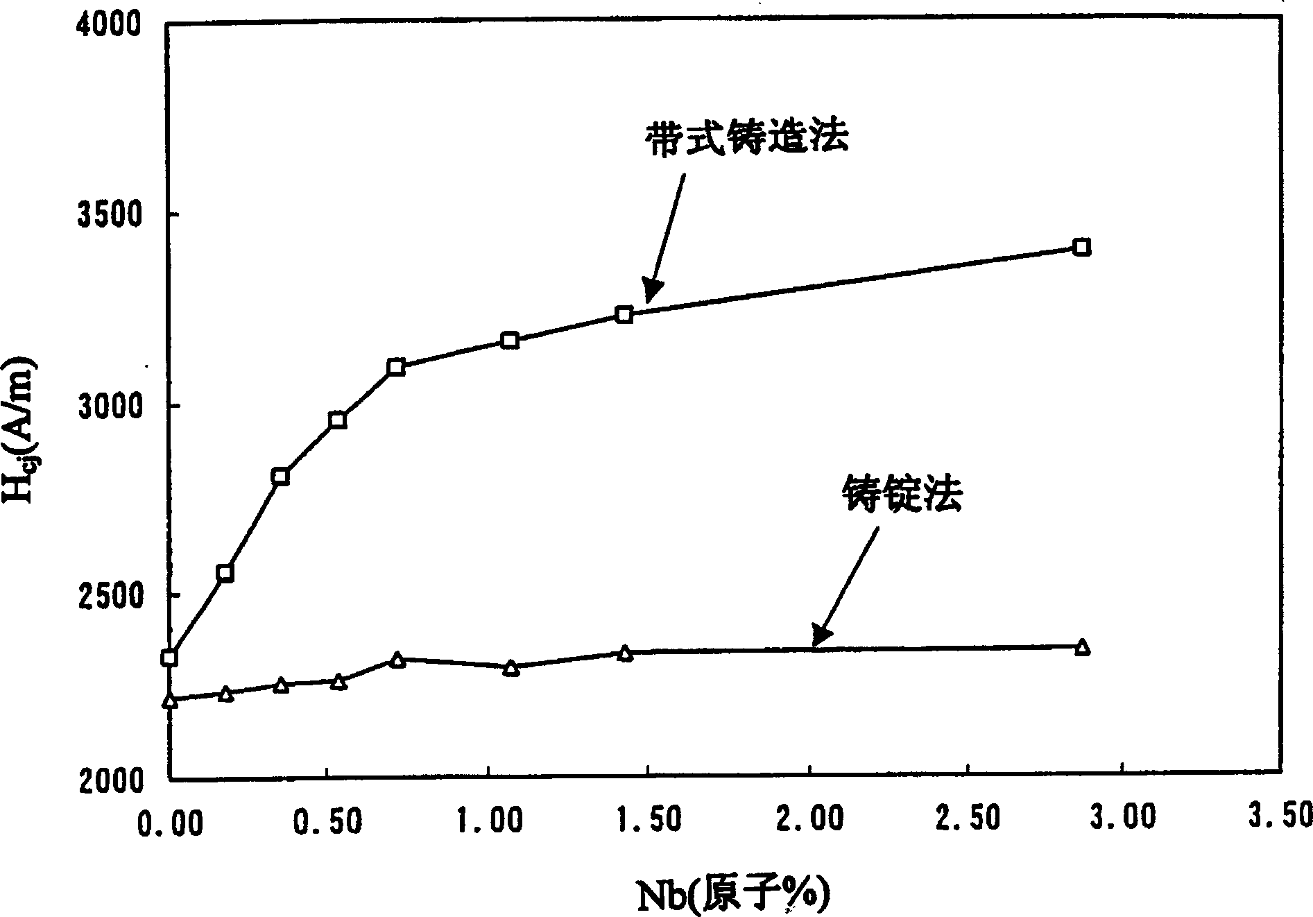
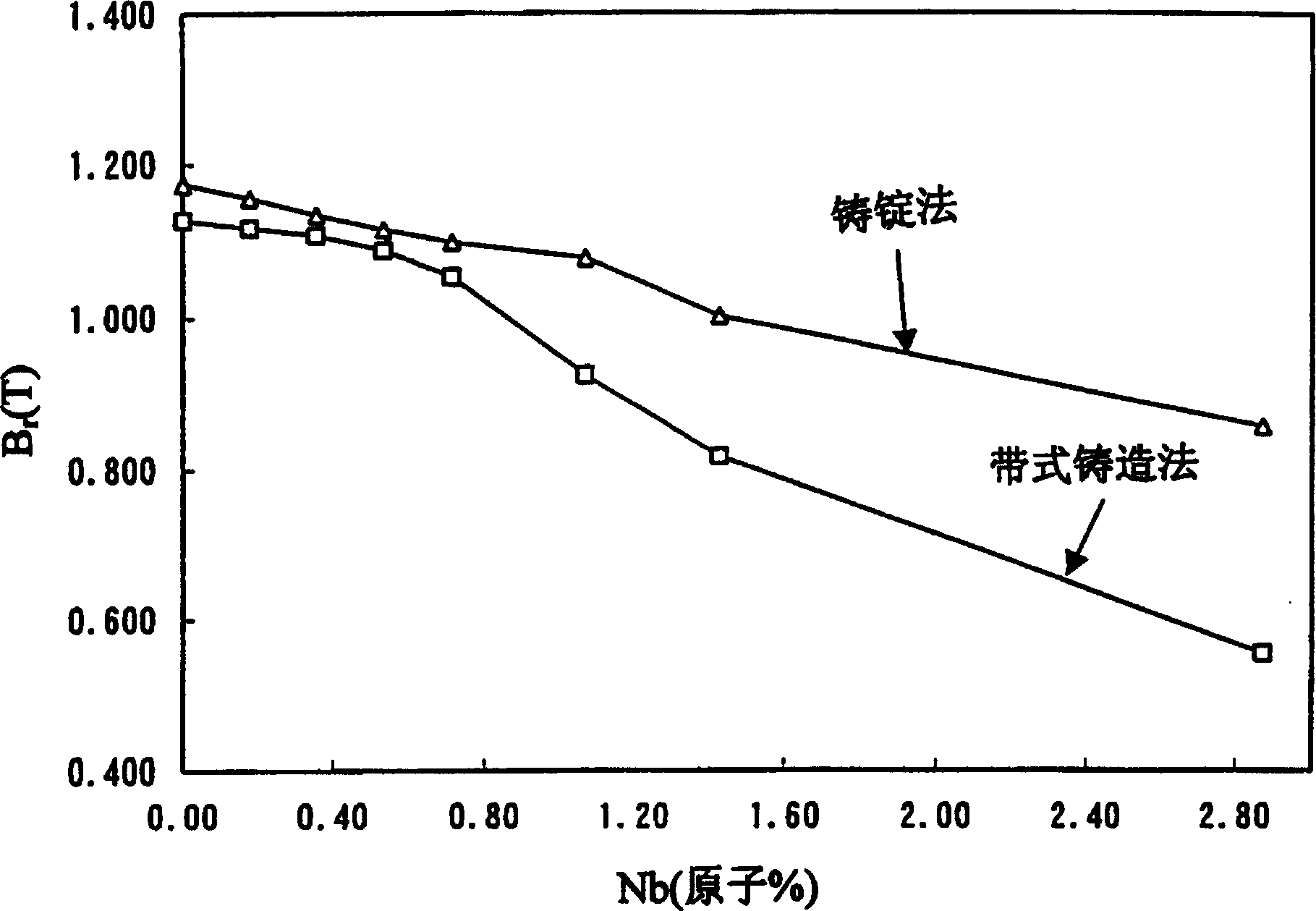
[0022] The present inventors found that, at 10 2 ~10 4 The cooling rate of K / s is used to rapidly cool the molten raw material alloy. When making a solidified alloy, only a small amount of Nb or Mo (less than 1.0 atomic % of the whole) is added, and these additives are evenly dispersed in the alloy structure, which can inhibit The remanent magnetic flux density and processability of the sintered magnets caused by the addition of metals to form borides are reduced, and the coercive force can be increased, and the squareness of the demagnetization curve can also be improved.

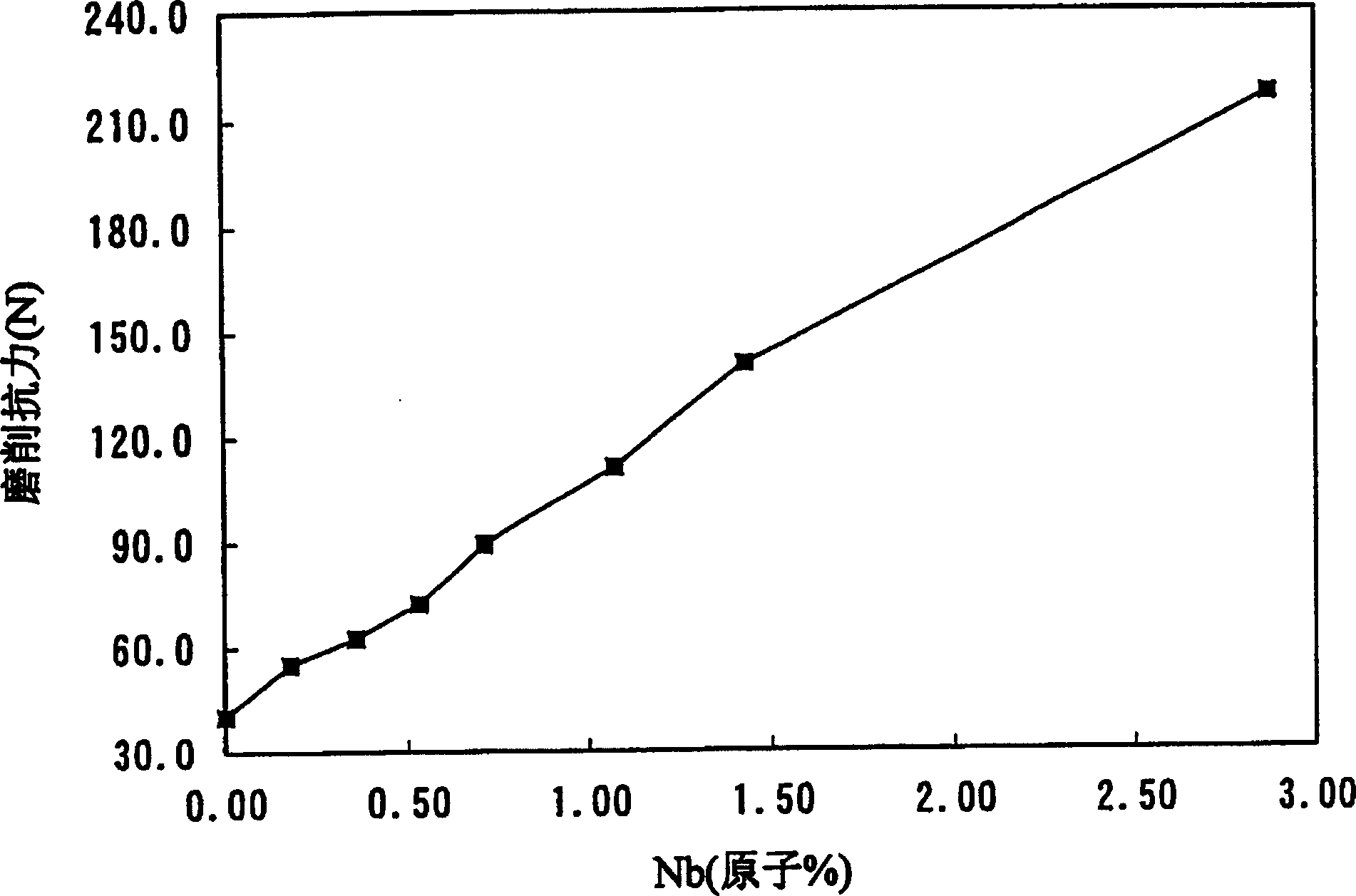
[0023] In the conventional ingot casting method, it is considered necessary to add a large amount of Nb or the like in order to increase the coercive force. However, when the strip casting method is used to produce the rapidly solidified alloy, if the same amount of Nb is added as in the past, the hardness of the final sintered magnet will be very high, resulting in the deformation of the surface grinding...


PUM

PropertyMeasurementUnit
thicknessaaaaaaaaaa
particle diameteraaaaaaaaaa
particle sizeaaaaaaaaaa

Abstract

A rapidly solidified alloy is produced by quenching and solidifying a melt of an alloy having a general formula represented by (Fe1-mTm)100-x-y-zQxRyMz where T denotes at least one kind of element selected from the group consisting of Co and Ni, Q denotes at least one kind of element selected from the group consisting of B and C, R denotes at least one kind of rare earth element, and M denotes at least one kind of element selected from the group consisting of Nb and Mo, and the mole fractions x, y, z, and m respectively satisfy 2<=x<=28 (atom %), 8<=y<=30 (atom %), 0.1<=z<1.0 (atom %), and 0<=m<=0.5 (atom %). The rapidly solidified alloy is then pulverized and sintered to manufacture a rare earth permanent magnet. The cooling rate is controlled to be in the range of 102 K / sec to 104 K / sec, so that the alloy structure is uniformly fine and the added element M is uniformly dispersed.

Description

technical field [0001] The present invention relates to a rare earth magnet and its manufacturing method. Background technique [0002] At present, when producing R-Fe-B type rare earth sintered magnets, it has been proposed to add Nb (niobium) to the raw material alloy in order to refine the crystal grain size of the sintered body and improve the heat resistance of the magnet. It is known that Nb suppresses the coarsening of crystal grains during sintering and improves the magnetization performance of the magnet. [0003] Japanese Unexamined Patent Publication No. 7-94311 discloses a technique for improving magnet performance and heat resistance by adding 0.1 to 2.0% by weight of Nb to Nd-Fe-Co-B type sintered magnets. [0004] In addition, it is announced in the Japanese Patent Publication No. 6-69003 that when the rare earth magnet alloy is produced by the ultra-quick cooling method, if 1 to 10 atomic % of metal elements (Ti, Zr, Hf, Nb and other metal elements) are adde...

Claims


Application Information

Patent Timeline
Patent Type & Authority Patents(China)
IPC IPC(8): H01F1/057H01F1/058
CPCH01F1/0573H01F1/0579H01F1/058B82Y25/00H01F1/0577
Inventor 李钢
Owner HITACHI METALS LTD
Learn More