Magnetic cell and magnetic memory

a magnetic memory and cell technology, applied in the field of magnetic memory and cell, can solve the problems of insufficient generation of magnetic field, difficult localization,

Active Publication Date: 2004-08-26
KIOXIA CORP
View PDF6 Cites 68 Cited by
  • Summary
  • Abstract
  • Description
  • Claims
  • Application Information

AI Technical Summary

Benefits of technology

0028] FIG. 4A and FIG. 4B show schematic section views for explaining the mechan...

Problems solved by technology

However, since the magnetic field fundamentally has the character to spread over a space, it is difficult to be made localized.
Moreover, if a generation source of the magnetic field is made small for the sake of making the magnetic field localized, the problem that the...

Method used


Image

  • Magnetic cell and magnetic memory
  • Magnetic cell and magnetic memory
  • Magnetic cell and magnetic memory

Examples


first embodiment

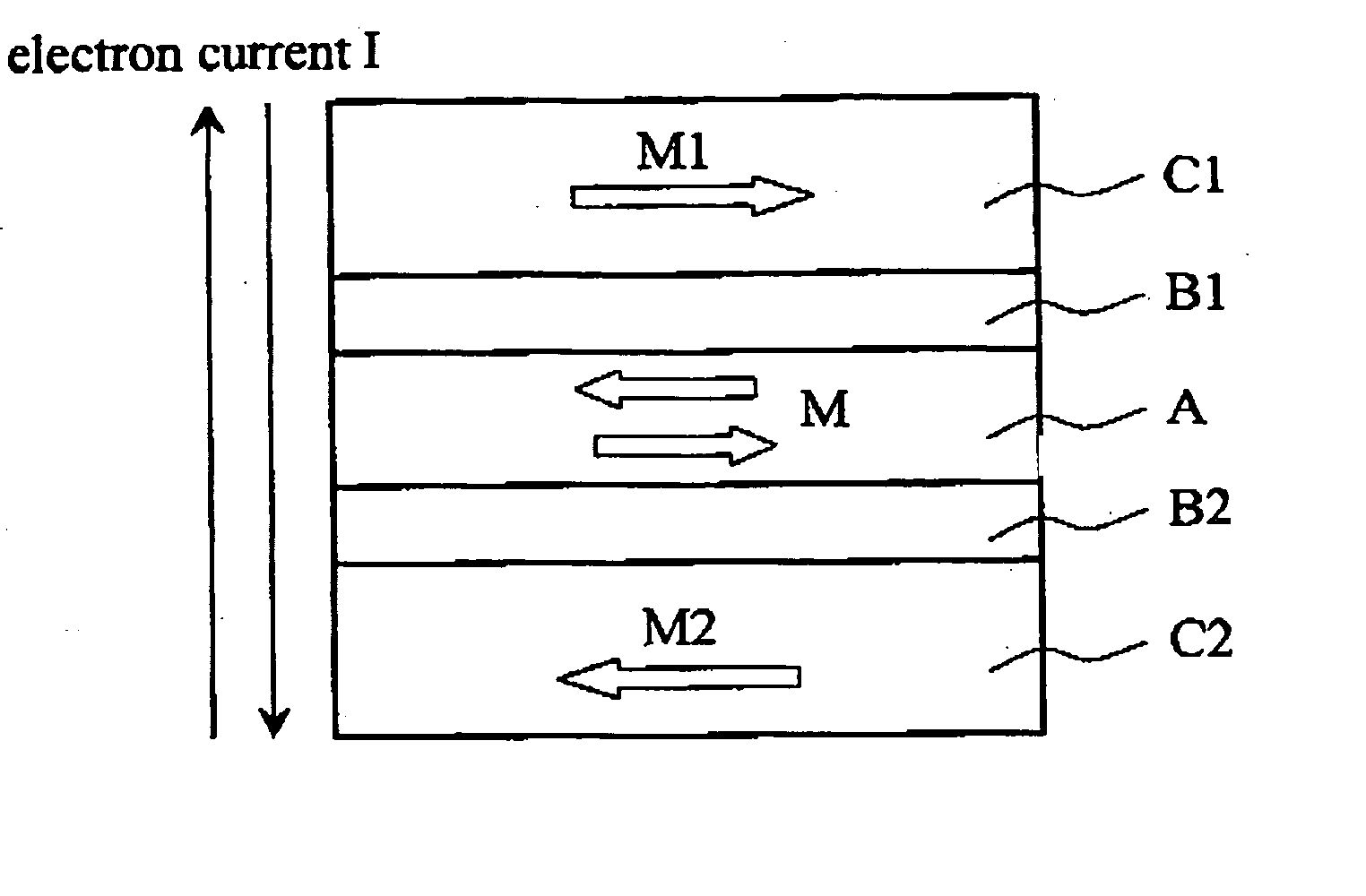
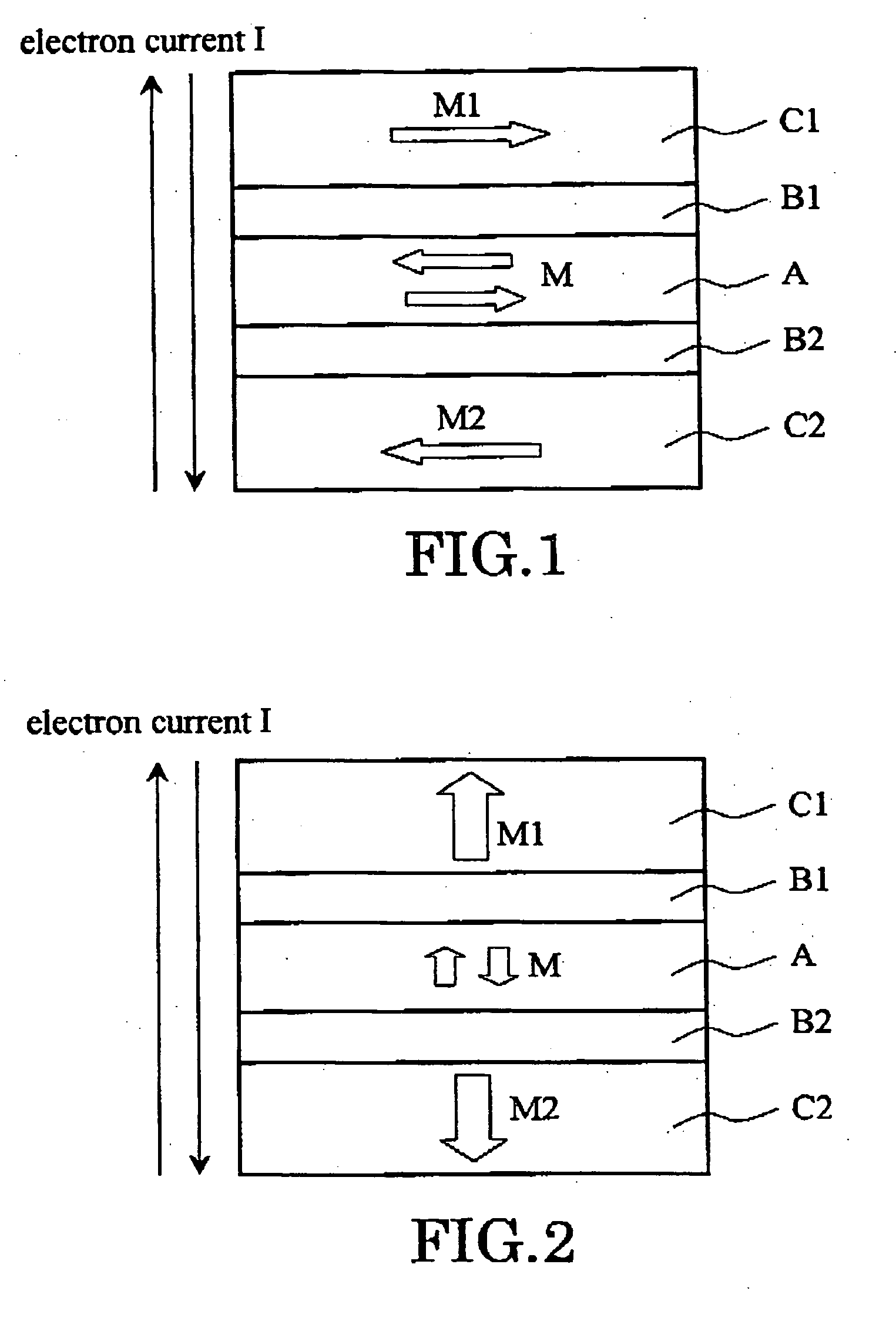
[0079] FIG. 1 is a schematic diagram which illustrates a fundamental cross-sectional structure of the magnetic cell according to the present invention. This magnetic cell has, two magnetically fixed layers (pinned layer) C1 and C2 whose magnetization directions M1 and M2 are anti-parallel, a magnetic recording layer (free layer) A whose magnetization direction can be changed, and intermediate layers B1 and B2 between the magnetic recording layer A and the magnetically fixed layers.

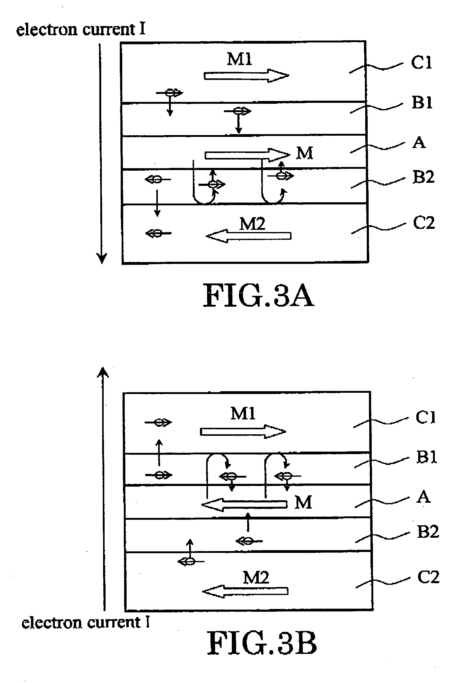
[0080] The magnetization direction M of the magnetic recording layer A can be controlled by passing current I between the upper magnetically fixed layer C1 and the lower magnetically fixed layer C2. Specifically, the magnetization direction M of the magnetic recording layer A can be reversed by changing direction (polarity) of the flow of the current I. In recording information, "0" and "1" are assigned respectively, according to the magnetization direction M.

[0081] And, in the magnetic cell of the present...

examples

[0217] Hereafter, the embodiment of the invention will be explained in more detail, referring to examples.

first example

[0218] FIG. 29A is a schematic diagram showing the principal cross-sectional structure of the magnetic cell of this example, and FIG. 29B is a schematic diagram showing the principal cross-sectional structure of the magnetic cell of the comparative example.

[0219] That is, the magnetic cell of this example (sample I) has the structure where the electrode EL 1, the magnetically fixed layer C1, the intermediate layer B1, the magnetic recording layer A, intermediate-layer B2, the magnetically fixed layer C2, and the electrode EL 2 are laminated. Moreover, the magnetic cell of the comparative example (sample II) has the structure where the electrode EL 1, the magnetic recording layer A, the intermediate layer B, the magnetically fixed layer C, and the electrode EL2 are laminated. The material and the thickness of each layer are as the following:

[0220] Sample I: EL1(Cu) / C1(Co:20 nm) / B1(Cu:10 nm) / A(Co: 3 nm) / B2(Cu:6 nm) / C2(Co:20 nm) / EL2 (Cu)

[0221] Sample II:EL1(Cu) / A(Co:3 nm) / B(Cu:6nm) / C (...


PUM


Abstract

A magnetic cell comprises: a first ferromagnetic layer whose magnetization is substantially fixed in a first direction; a second ferromagnetic layer whose magnetization is substantially fixed in a second direction opposite to the first direction; a third ferromagnetic layer provided between the first and the second ferromagnetic layers, a direction of magnetization of the third ferromagnetic layer being variable; a first intermediate layer provided between the first and the third ferromagnetic layers; and a second intermediate layer provided between the second and the third ferromagnetic layers. The direction of magnetization of the third ferromagnetic layer can be determined under an influence of spin-polarized electrons upon the third ferromagnetic layer by passing a current between the first and the second ferromagnetic layers.

Description

[0001] This application is based upon and claims the benefit of priority from the prior Japanese Patent Application No. 2002-342447, filed on Nov. 26, 2002; the entire contents of which are incorporated herein by reference.[0002] The present invention relates to a magnetic cell and a magnetic memory, and more particularly, it relates to a magnetic cell and a magnetic memory which can be written-in by passing spin-polarized electrons.[0003] Conventionally, in order to control the direction of magnetization of a magnetic material, the method of applying a magnetic field to the magnetic material has been taken. For example, in the case of the hard disk drive, writing-in is carried out by reversing the magnetization direction of a medium by applying a magnetic field generated from a recording head. Moreover, in a solid-state magnetic memory, the magnetization direction of a cell is controlled by applying a current-induced magnetic field generated by passing a current to the wirings prov...

Claims


Application Information

Patent Timeline
IPC IPC(8): G11C11/15
CPCG11C11/15G11C11/16G11C11/5607H01L27/228H01L43/08H01L27/224H10B61/10H10B61/22H10N50/10
Inventor NAKAMURA, SHIHOHANEDA, SHIGERUOHSAWA, YUICHI
Owner KIOXIA CORP
Why Eureka
Try Eureka