

Pin tray dental prostheses modeling system with re-usable tray
a technology of dental prostheses and trays, which is applied in the field of pin tray dental prostheses modeling systems with reusable trays, can solve the problems that the exterior surfaces of the prosthesis cannot simply replicate the surface of the die segment, and achieve the effects of facilitating the placement of the pinned die segment within the trays, minimizing the number of different type parts, and quick and easy removal
- Summary
- Abstract
- Description
- Claims
- Application Information
AI Technical Summary
Benefits of technology
Problems solved by technology
Method used
Image

Examples
Embodiment Construction
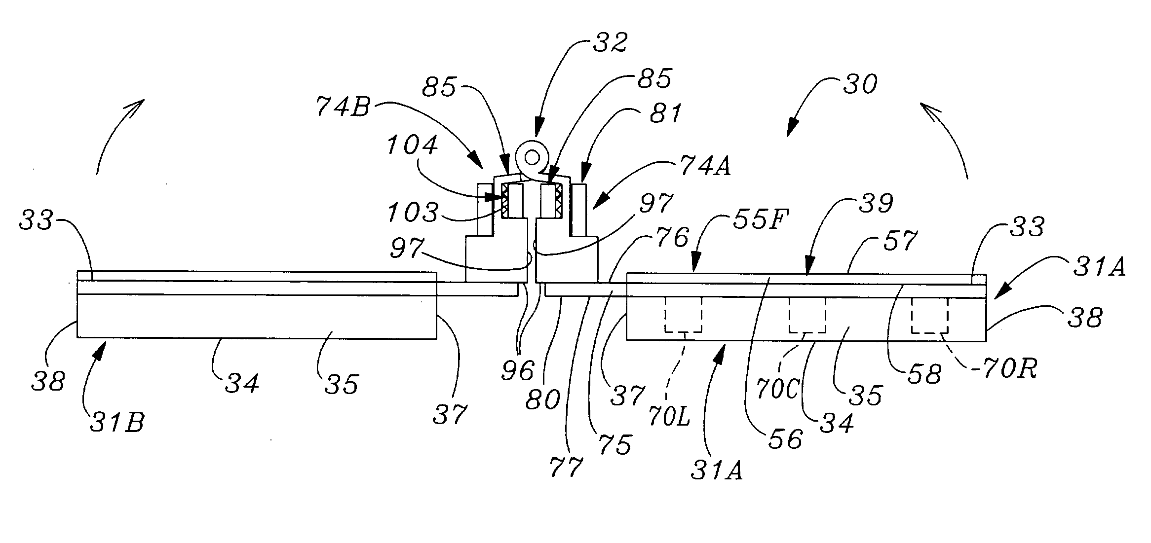
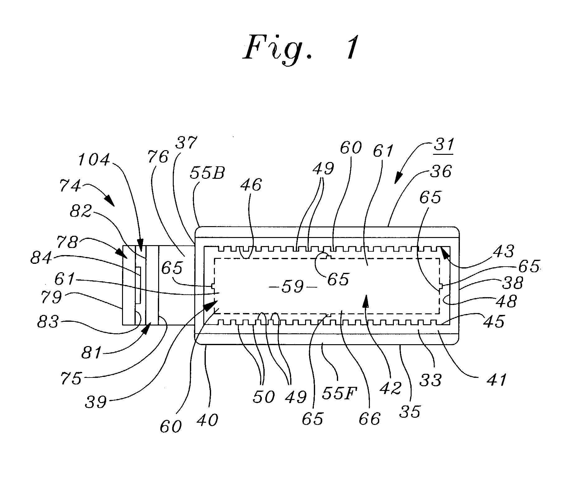
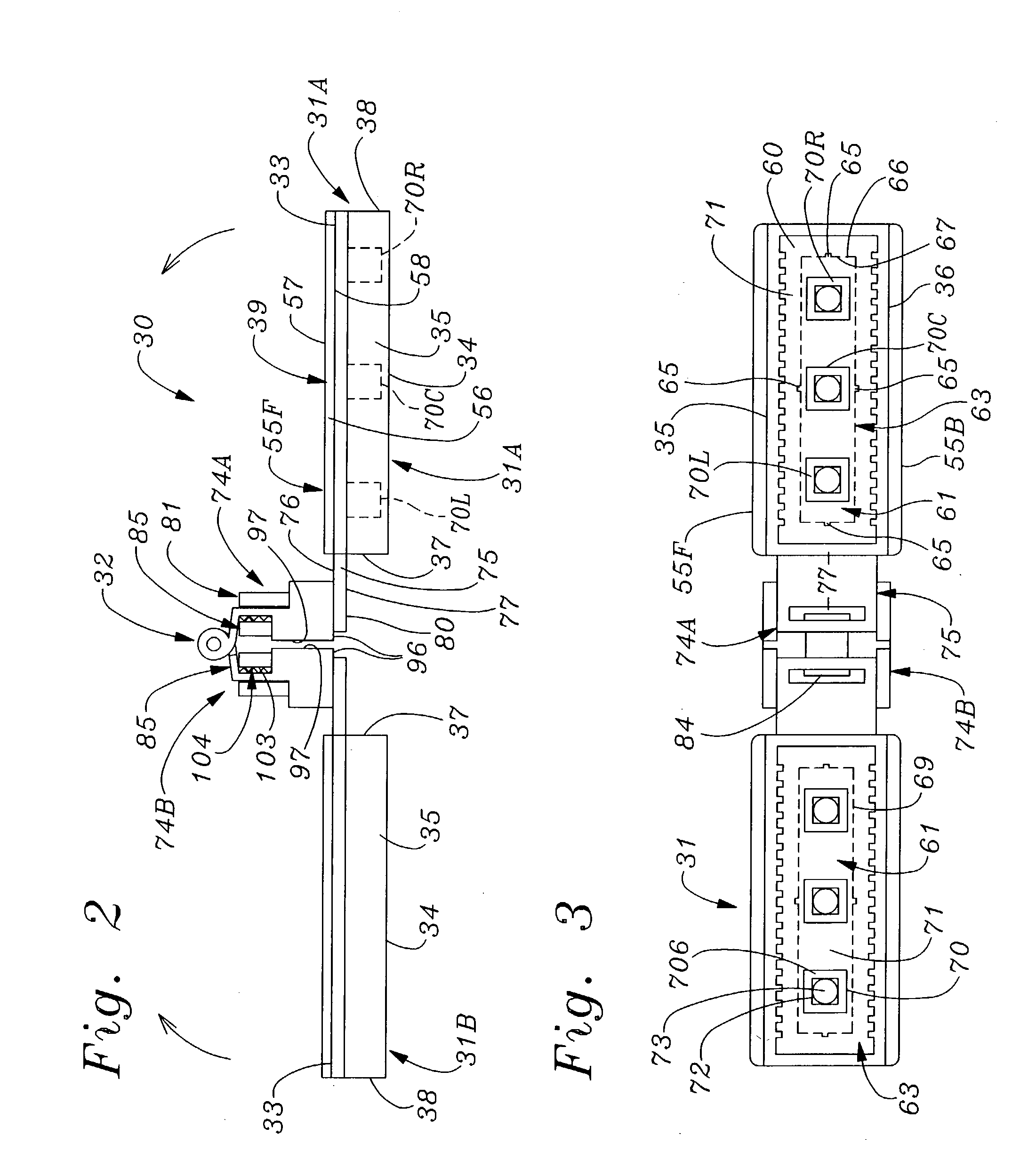
[0079] Referring now to FIGS. 1-3, an apparatus 30 for making pin-tray dental prostheses models according to the present invention may be seen to include a pair of molding trays 31A, 31B which are releasably connectable by a hinge mechanism 32 and used for fabricating and holding dental models made according to the present invention. As shown in FIG. 16 and as will be described in detail below, hinge mechanism 32 enables trays 31A, 31 B to be pivoted between a mutually co-planar horizontally disposition as shown in FIG. 2, to a configuration in which one of the molding trays overlies the other in a generally parallel disposition, as shown in FIGS. 2 and 16.
[0080] As will be made clear in the ensuing description, only one of molding trays 31A, 31B need by provided with certain novel structural features according to the present invention, if a removable dental model cast is to be made of teeth in a single jaw of a patient. However, according to a preferred method of practicing to the ...
PUM
 Abstract
Description
Claims
Application Information