Al technical title is built by PatSnap Al team. It summarizes the technical point description of the patent document.
a trap and rock technology, applied in the field of rock simulating pest traps, can solve the problems of large outer housings, undesirable placement of traps in residences and businesses, and large number of homeowners
Inactive Publication Date: 2004-10-14
J L INNOVATIONS
View PDF55 Cites 11 Cited by
Summary
Abstract
Description
Claims
Application Information
AI Technical Summary
This helps you quickly interpret patents by identifying the three key elements:
Problems solved by technology
Method used
Benefits of technology
0014] In the preferred embodiment, the rear edge of the lid member is pivotally attached to the rear edge of the bottom member. The mating perimeter edges of the b...
Problems solved by technology
Because deadly diseases and filthy conditions are often associated with insects and rodents, the placement of traps inside residences and businesses where they may be in plain view of guests or visitors is undesirable.
One drawback of such traps is that the outer housings are relatively large structures that are visible at a di...
Method used
Image
Click on the blue label to locate the original text in one second.
Reading with bidirectional positioning of images and text.
Examples
Embodiment Construction
)
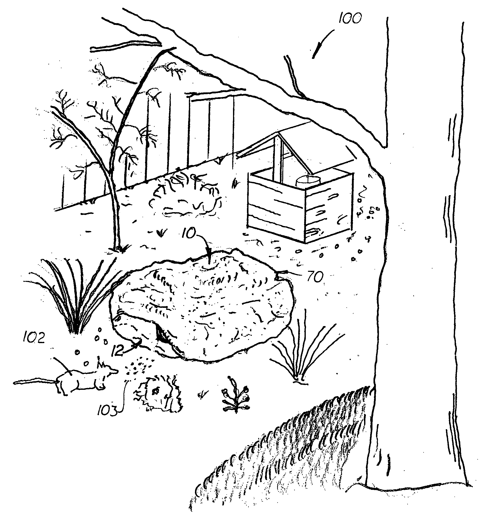
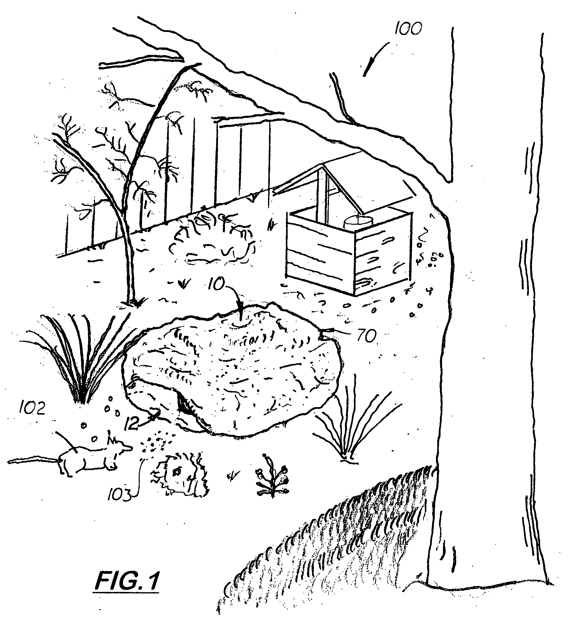
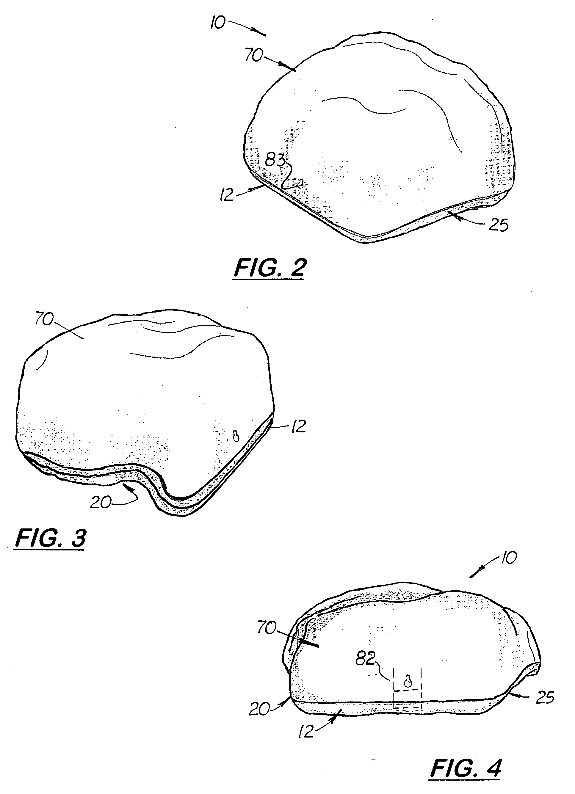
[0027] Referring to FIG. 1-11, there is, shown and described a pest trap 10 designed to simulate a rock in a garden or landscape area 100. The pest trap 10 includes a substantially flat bottom member 12 and a dome-shaped upper lid member 70. The bottom member 12 and lid member 70 are complimentary in shape so that when the lid member 12 is aligned and registered over the bottom member 70, a simulating three--dimensional rock-shaped structure.
[0028] Formed on opposite sides of the bottom member 12 are two, inward extending tunnel cavities 18, 23. Each tunnel cavity 18, 23 are concave in cross-section and curves slightly rearward and centrally on the bottom member 12. When the trap 10 is placed on the ground 101, the tunnel cavities 18, 23 form two tunnels 20, 25 on opposite sides of the outer housing 11 that leads into a large cavity 65 formed inside the structure. The perimeter edge of the bottom member 12 adjacent to each tunnel cavity 18, 23 is irregular and concave thereby formi...
PUM
Abstract
A tamper-resistant pest trap that has an outer housing that simulates a rock typically found in a garden or landscape area around a residence or building. The outer housing includes a substantially flat bottom member and a pivotally attached upper dome-shaped lid member. When the lid member is closed over the bottom member, a large cavity is formed inside the trap. Formed on the bottom member are two, inward extending tunnel cavities that form two partially concealed tunnels that extend under the trap when the trap is placed on the ground. Formed on the perimeter edge of the outer housing is an outer pest opening. From on the bottom member directly over the tunnel cavity is an inner pest opening that allows a rodent to enter the large cavity after traveling through the tunnel. Formed inside the outer housing is a holding tray designed to hold a rodenocide or a mechanical trap capable of killing the rodent. An optional bait paper tray is also formed in the bottom member to hold bait paper. An optional lock is provided to prevent tampering and stake and hold-down chain are provided to attach the trays to the ground
Description
[0001] This is a continuation-in-part patent application based on the utility patent application (Ser. No. 09 / 929,779) filed on Aug. 14, 2001 and based on the provisional patent application (Serial No. 60 / 241,244) filed on Oct. 18, 2000.[0002] 1. Field of the Invention[0003] This invention pertains to pest traps, and, in particular, to pest traps designed to be used in outdoor, visible areas.[0004] 2. Description of the Related Art[0005] Most home and business owners would prefer to place pest traps, when needed, outside their residence or business. Because deadly diseases and filthy conditions are often associated with insects and rodents, the placement of traps inside residences and businesses where they may be in plain view of guests or visitors is undesirable.[0006] In order to use a pest trap outdoors, a protective outer housing is used which houses the poisoned bait or body-piercing trap. Such traps are disclosed in U.S. Pat. Nos. 4,541,198, 4,550,525, 4,611,426, 4,730,412, 5,...
Claims
Application Information
Patent Timeline
Application Date:The date an application was filed.
Publication Date:The date a patent or application was officially published.
First Publication Date:The earliest publication date of a patent with the same application number.
Issue Date:Publication date of the patent grant document.
PCT Entry Date:The Entry date of PCT National Phase.
Estimated Expiry Date:The statutory expiry date of a patent right according to the Patent Law, and it is the longest term of protection that the patent right can achieve without the termination of the patent right due to other reasons(Term extension factor has been taken into account ).
Invalid Date:Actual expiry date is based on effective date or publication date of legal transaction data of invalid patent.