Liquid ring pump

a technology of ring pump and liquid cylinder, which is applied in the direction of pump components, liquid fuel engine components, liquid fuel engines, etc., can solve the problems of negative impact on costs and negatively affect the efficiency of liquid ring pump a

Inactive Publication Date: 2004-10-14
BALLARD POWER SYSTEMS
View PDF21 Cites 4 Cited by
  • Summary
  • Abstract
  • Description
  • Claims
  • Application Information

AI Technical Summary

Problems solved by technology

This limitation with liquid ring pump A's design results in tight tolerances having to be attained with respect to the value of clearance C.sub.L, which has a negative impact on the costs of liquid ring pump A. Furthermore, liquid ring pump A's design is not amenable to having foreign substances being introduced in the compression zones 5.
Indeed, dirt finding its way in compression zones 5 would likely also find its way to clearance C.sub.L which, because of the small dimensions involved, would negatively impact liquid ring pump A's efficiency as friction forces would increase.

Method used


Image

  • Liquid ring pump
  • Liquid ring pump
  • Liquid ring pump

Examples


Embodiment Construction

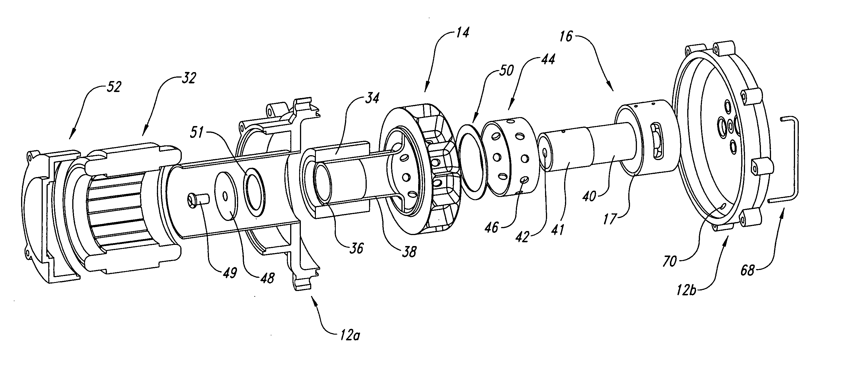
[0033] Many specific details of certain embodiments of the invention are set forth in the detailed description below, and illustrated in enclosed FIGS. 4-10, to provide a thorough understanding of such embodiments. One skilled in the art, however, will understand that the present invention may have additional embodiments, or may be practiced without several of the details described.

[0034] FIGS. 4 and 5 illustrate a liquid ring pump 10 according to one embodiment of the present invention. Liquid ring pump 10 generally incorporates a housing 12A and 12B (also shown in FIG. 6), an annular rotor 14 (also shown in FIG. 7) and an intake-discharge port assembly 16 (also shown in FIGS. 8A and 8B).

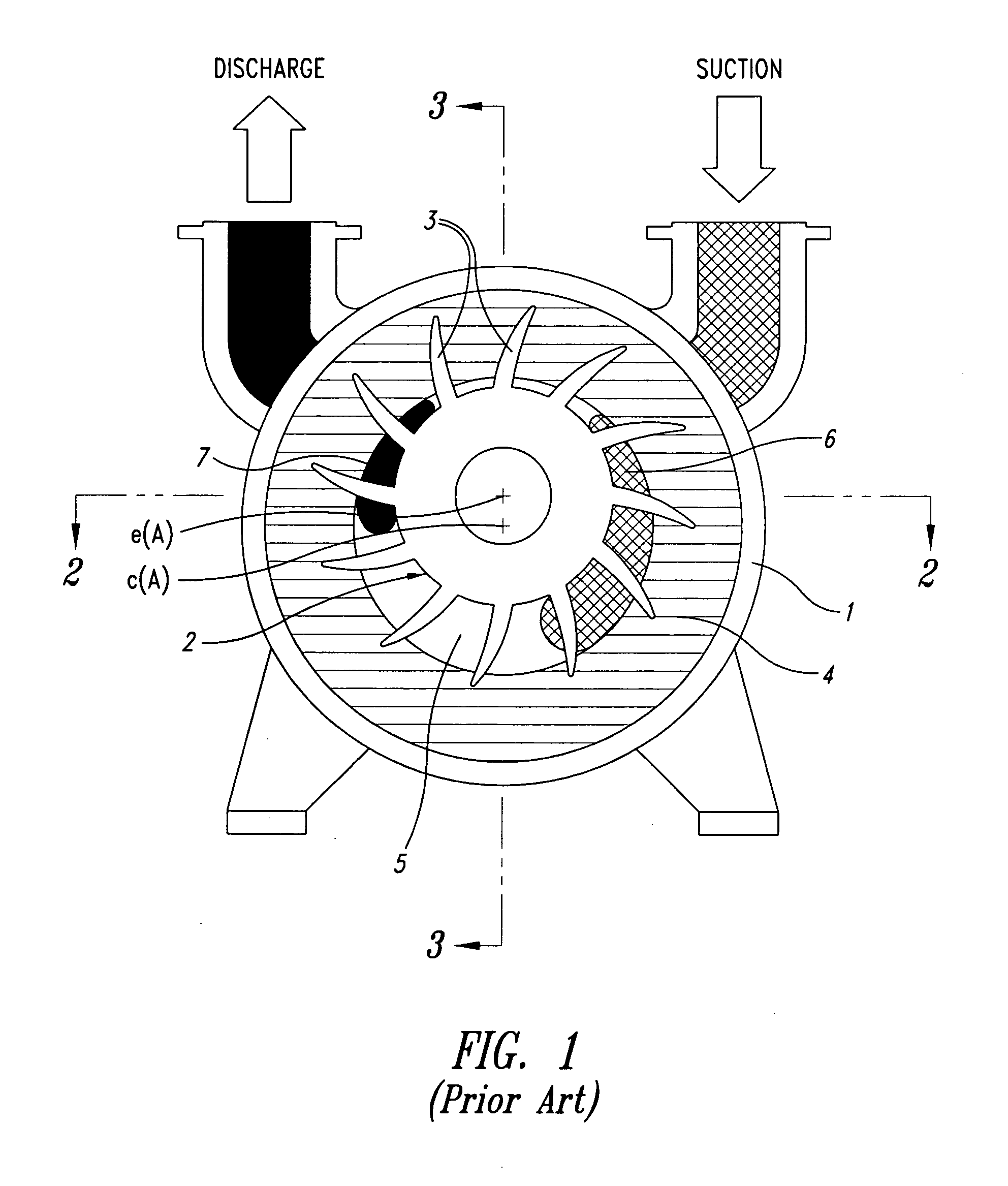
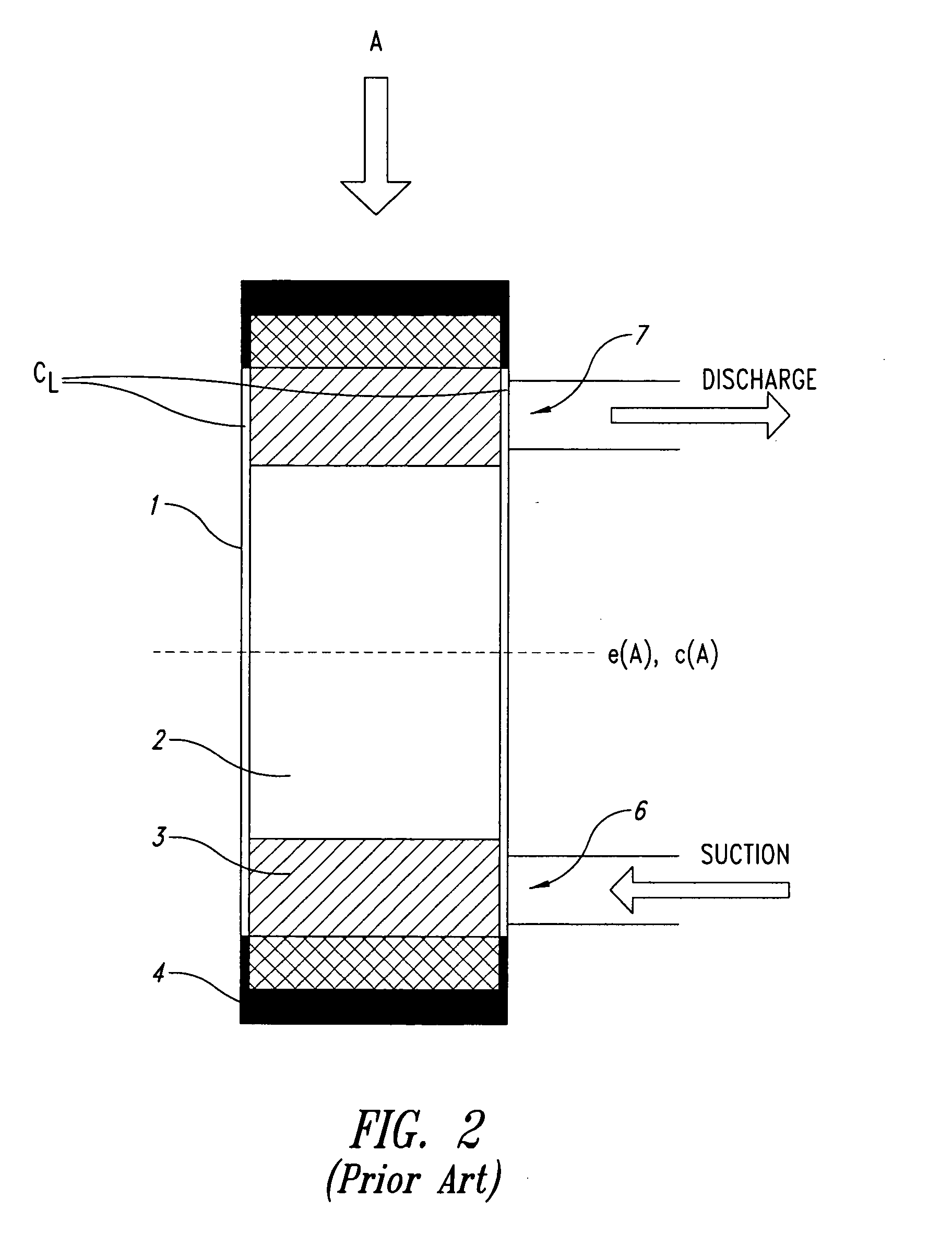
[0035] In the current embodiment, housing 12A / 12B is a 2-part element which, when connected to one another, forms an inner annular surface 18. Rotor 14 is mounted eccentrically within housing 12A / 12B, i.e., axis of rotation e(B) of rotor 14 does not align with geometric center axis c(B) of housing ...


PUM


Abstract

The invention provides devices, systems and methods for use in compressing and/or pumping gases or vapors using a fluid ring pump. In one embodiment, a rotor is provided for being rotatably mounted eccentrically within a housing on a liquid ring pump. The rotor comprises an annular inner surface having a plurality of radial apertures and a plurality of walled cells. The walled cells project radially outward from the annular inner surface. A wall on each of the walled cells extend around at least one of the radial apertures.

Description

[0001] This application claims the benefit of U.S. Provisional Patent Application No. 60 / 440,892, filed Jan. 17, 2003, where this provisional application is incorporated herein by reference in its entirety.[0002] 1. Field of the Invention[0003] The present invention relates to pumps and compressors, and more particularly, to liquid ring pumps and compressors.[0004] 2. Background of the Invention[0005] A liquid ring pump operates on the rotary liquid piston principle. A typical liquid ring pump A is shown in FIGS. 1 to 3. As shown in FIG. 1, which is a schematic side view of liquid ring pump A, it consists of an annular housing 1, within which is eccentrically mounted a rotor 2 with radially extending and angularly spaced blades 3. During operation of liquid ring pump A, a working liquid introduced in housing 1 is forced outwardly by the rotating blades, thereby forming a liquid ring 4 concentric to housing 1. Gas is introduced in compression zones 5, which is defined as the spaces b...

Claims


Application Information

Patent Timeline
Patent Type & Authority Applications(United States)
IPC IPC(8): F04C19/00F04C29/00
CPCF04C19/005F04C19/008F04C29/0085
Inventor BARTON, RUSSELL H.
Owner BALLARD POWER SYSTEMS
Why Eureka
Try Eureka