DNAPL contaminated underground water in-situ remediation method

An in-situ remediation and groundwater technology, applied in the direction of contaminated groundwater/leachate treatment, water pollutants, water/sewage treatment, etc., can solve problems such as inability to determine the extraction location, DNAPL pollution, limited extraction depth, etc. Achieve the effects of simple and easy repair steps, light equipment, water and electricity saving

Inactive Publication Date: 2018-07-24
NANJING INST OF ENVIRONMENTAL SCI MINIST OF ECOLOGY & ENVIRONMENT OF THE PEOPLES REPUBLIC OF CHINA
View PDF7 Cites 5 Cited by
  • Summary
  • Abstract
  • Description
  • Claims
  • Application Information

AI Technical Summary

Problems solved by technology

[0009] Aiming at the shortcomings existing in the prior art when extracting DNAPL, the extraction depth is limited, the extraction position cannot be determined, and the extraction is not thorough, etc., the present invention provides an in-situ repair method for groundwater polluted by DNAPL

Method used


Image

  • DNAPL contaminated underground water in-situ remediation method
  • DNAPL contaminated underground water in-situ remediation method

Examples


Embodiment 1

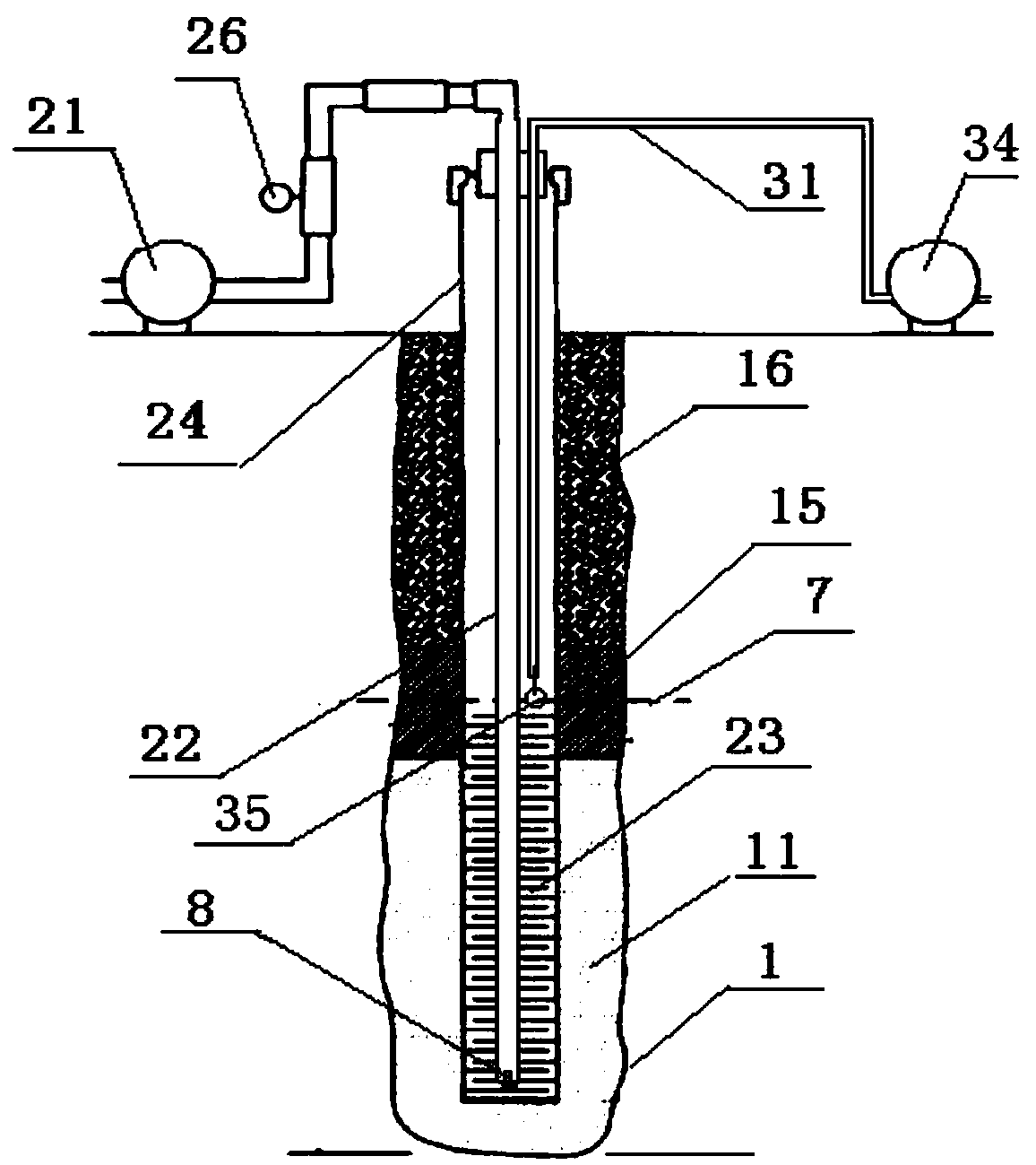
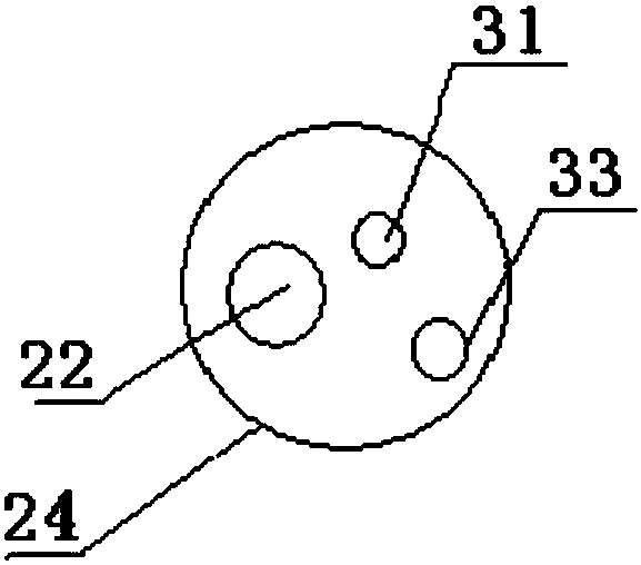
[0043] Such as figure 1 As shown, a kind of in-situ remediation system for groundwater polluted by DNAPL in this embodiment includes a drilling 1, a filtering device and a single pump extraction device, and also includes a water injection device; wherein: the filtering device includes a concrete layer 16, bentonite layer 15 and sand filling layer 11, and are sequentially set in the drilling 1 from top to bottom; the static water level line 7 is set in the bentonite layer 15; the single pump extraction device includes a liquid ring pump 21, a pumping Lifting pipe 22, grid screen pipe 23 and well pipe 24, wherein: the liquid ring pump 21 is a water ring vacuum pump, the model is 2BV2 060, and the flow rate is 27m 3 / h, the vacuum degree is 20000 Pa, the power is 1.1kw, and the rated voltage is 380V; the grid screen pipe 23 and the well pipe 24 are connected as a whole to pass through the concrete layer 16 and the bentonite layer 15 and be buried in the sand filling layer 11, An...

Embodiment 2

[0052] The basic structure of the in-situ remediation system for DNAPL-contaminated groundwater in this embodiment is the same as that in Embodiment 1, except that the liquid ring pump 21 has a model number of 1WZB-35; the lift in front of the pump is 6m;

[0053] An in-situ remediation system for DNAPL-contaminated groundwater in this embodiment was applied to a decommissioned factory in Nanjing. After testing, the groundwater level of the site was about 1.38m, the water surface was about 1.3m, and there was 0.8m thick DNAPL under the water surface;

[0054] A method for in-situ remediation of groundwater polluted by DNAPL in this embodiment, the basic steps are the same as those in Example 1, the difference is that the well is drilled to a depth of 6m; before the extraction starts, the floating matter is extracted, and the floating matter is basically extracted After the completion, lower the mouth of grid screen pipe 23 to the bottom of the well; after the extraction starts,...


PUM

PropertyMeasurementUnit
particle diameteraaaaaaaaaa

Abstract

Belonging to the technical field of soil and underground water pollution control, the invention discloses a DNAPL (dense non-aqueous phase liquid) contaminated underground water in-situ remediation method. A DNAPL contaminated underground water in-situ remediation system comprises a drilling well, a filtering device, a single-pump extraction device and a water injection device. The filtering device comprises a concrete layer, a bentonite layer and a sand-filling layer that are arranged in the drilling well from top to bottom in order. The single-pump extraction device comprises a liquid ring pump, an extraction pipe, a grid type sieve pipe and a well pipe. The water injection device comprises a water injection pipe, a vent hole and a water injection pump. One end of the water injection pipe is inserted into the well pipe, and the other end is connected to the water injection pump on the ground and is fixed to the upper end face of the well pipe. The vent hole is arranged at the upper end face of the well pipe. The DNAPL contaminated underground water in-situ remediation method provided by the invention solves the problems of limited extraction depth, difficult determination of extraction location, incomplete extraction and the like in the prior art, and has the advantages of wide application, high extraction efficiency and the like.

Description

[0001] The application of the present invention is a divisional application, the application number of the parent application: 2014108173333; the name of the parent application: an in-situ repair system for groundwater polluted by DNAPL and its application method; the application date of the parent application: 2014-12-24. technical field [0002] The invention belongs to the technical field of soil and groundwater pollution control, and in particular relates to an in-situ repair method for groundwater polluted by DNAPL. Background technique [0003] Soil and groundwater pollution refers to the intentional or unintentional application of substances harmful to humans and other living organisms into the soil due to human factors, so that the content of a certain component exceeds the self-purification capacity of the soil and groundwater or is significantly higher than that of the soil and groundwater environment. benchmarks or soil and groundwater environmental standards, and ...

Claims


Application Information

Patent Timeline
Patent Type & Authority Applications(China)
IPC IPC(8): C02F1/00C02F101/30C02F103/06
Inventor 王磊龙涛林玉锁陈樯祝欣
Owner NANJING INST OF ENVIRONMENTAL SCI MINIST OF ECOLOGY & ENVIRONMENT OF THE PEOPLES REPUBLIC OF CHINA
Why Eureka
Try Eureka