Method For Operating A Fuel Cell System And Fuel Cell System

a fuel cell and system technology, applied in the direction of fuel cells, solid electrolyte fuel cells, electrical equipment, etc., can solve the problems of adversely affecting their operation and reliability, and achieve the effect of low cost of a fuel cell system

Inactive Publication Date: 2007-12-06
SIEMENS AG
View PDF2 Cites 4 Cited by
  • Summary
  • Abstract
  • Description
  • Claims
  • Application Information

AI Technical Summary

Benefits of technology

[0009] The invention in this case utilizes the working principle of a liquid ring pump, in which during compression of the gas a mixing of the gas with the operating liquid of the liquid ring pump occurs. By virtue of the intimate mixing with the operating liquid, impurities are separated in the operating liquid. Impurities are, for example, accumulated particles or salts clinging to aerosols and dust particles, such as occur above all in an intake of sea air. These impurities are therefore prevented from passing into the gas compartments of the fuel cells and adversely affecting their operation and reliability. The impurities that are washed out of the air in this case accumulate in the operating liquid.
[0014] To improve the operating capability, in particular the efficiency of the purifying device, in an advantageous development it is provided that the operating liquid is supplied via a heat exchanger to the purifying device. The heat exchanger therefore effects a tempering, in particular a cooling, of the operating liquid in order to guarantee the operating capability of the ion exchanger.
[0017] To keep the construction compact and therefore keep the cost of a fuel cell system as low as possible, it is preferably further provided that the operating liquid of the liquid ring pump is used simultaneously as cooling water for the fuel cell system.

Problems solved by technology

These impurities are therefore prevented from passing into the gas compartments of the fuel cells and adversely affecting their operation and reliability.

Method used


Image

  • Method For Operating A Fuel Cell System And Fuel Cell System
  • Method For Operating A Fuel Cell System And Fuel Cell System
  • Method For Operating A Fuel Cell System And Fuel Cell System

Examples


Embodiment Construction

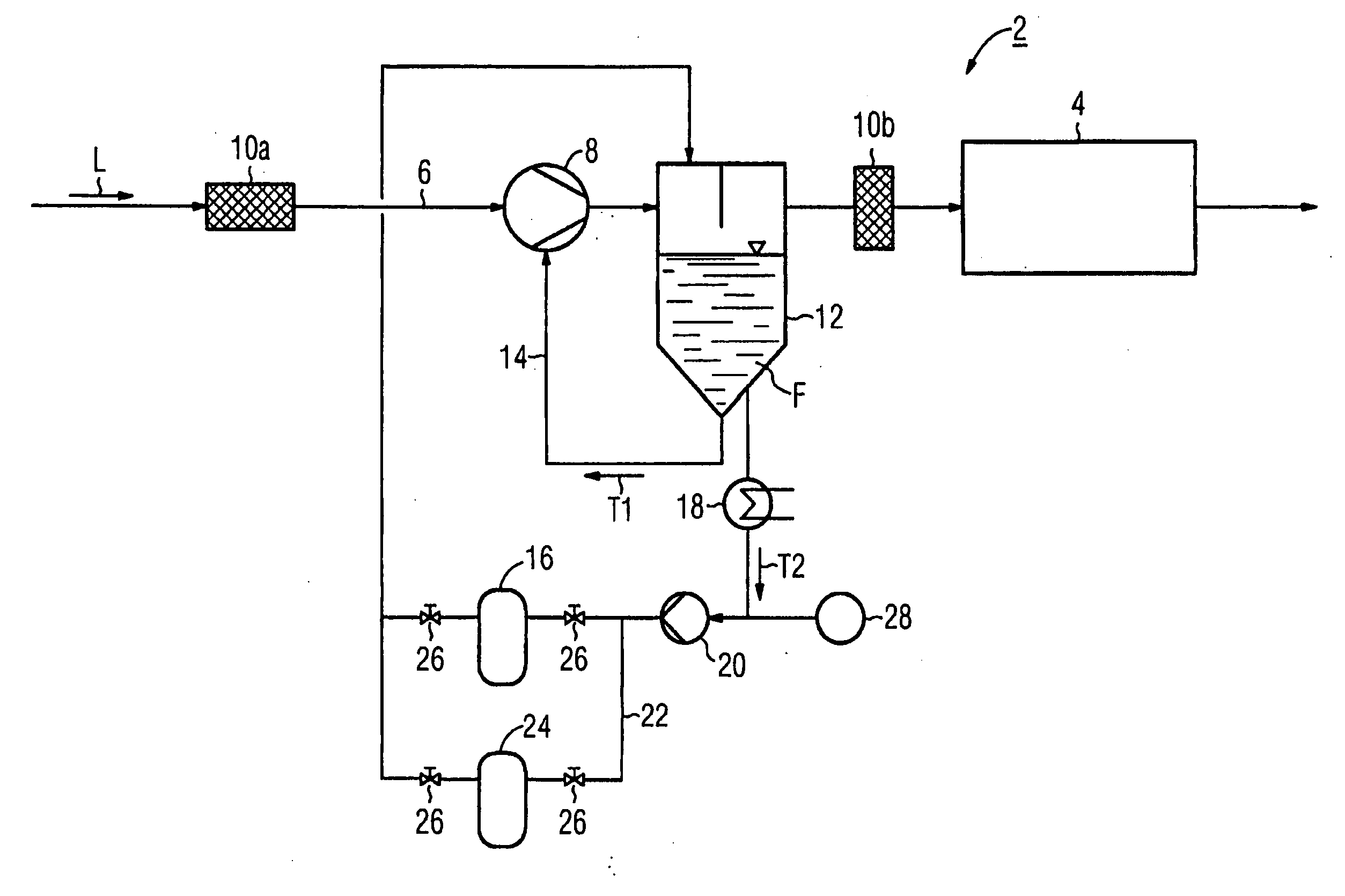
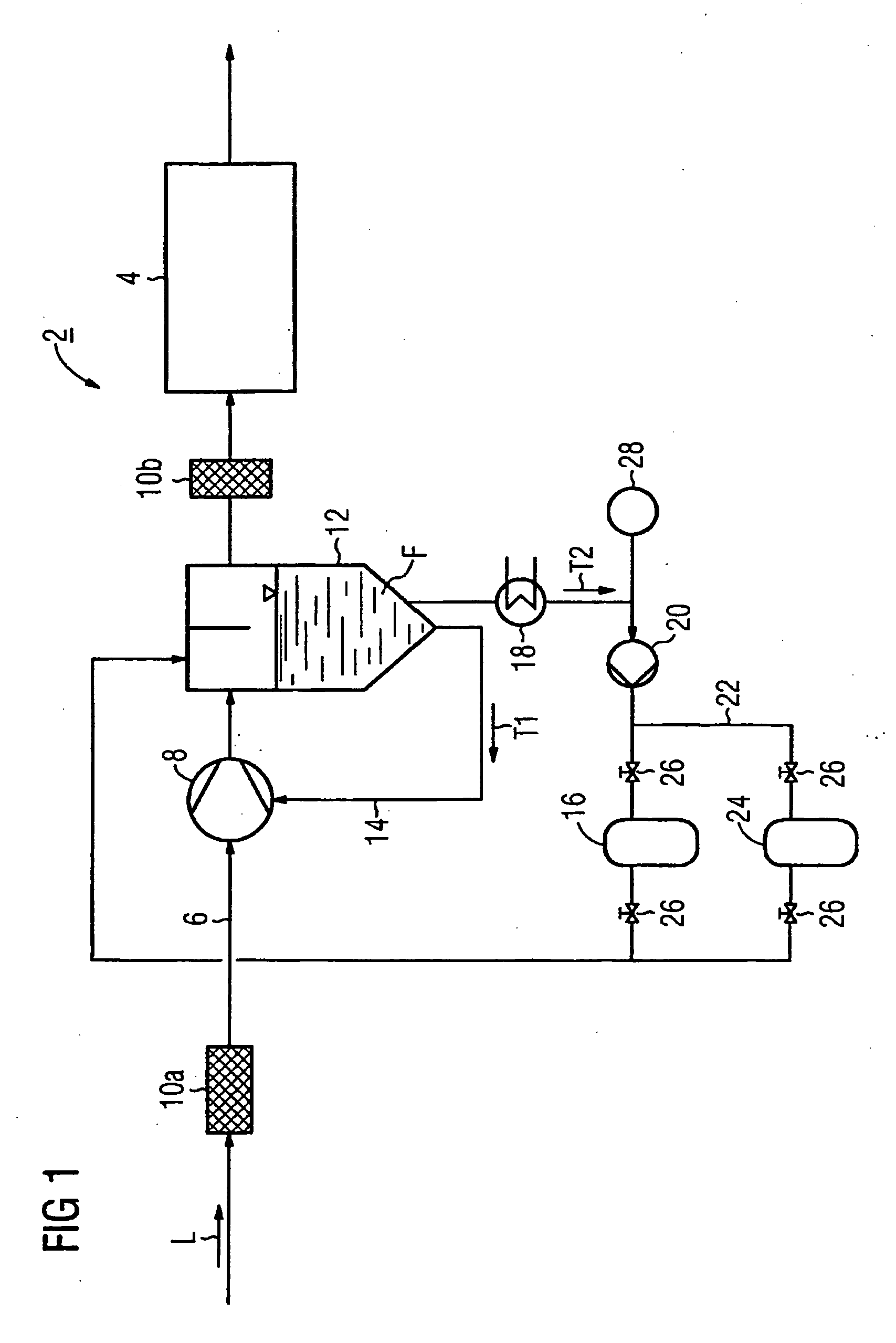
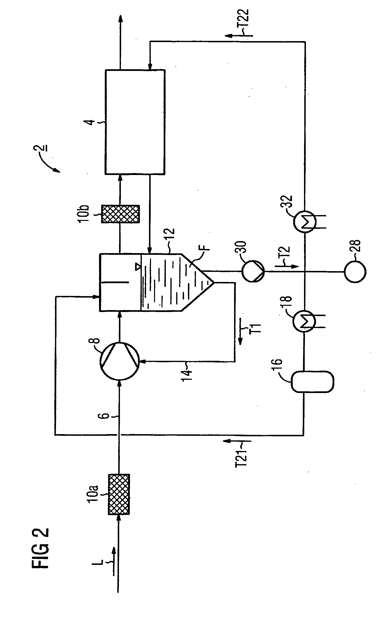
[0023] A fuel cell system 2 according to FIGS. 1 and 2 comprises a fuel cell block 4, which comprises a plurality of individual stacked fuel cells. In particular, for this purpose PEM fuel cells are used. A process gas, in this case ambient air L, is supplied through a feed line 6 to the fuel cell block 4. A fuel gas, for example hydrogen, is moreover supplied to the fuel cell block 4 in a manner not represented here.

[0024] Disposed in the feed line 6 is a liquid ring pump 8, which is also known as a water ring compressor. During operation, the air L is taken in through a first filter 10a, compressed in the liquid ring pump 8 and fed via a water separator 12 and a second filter 10b to the fuel cell block 4. From the water separator 12 an operating liquid F of the liquid ring pump 8 is fed through a return line 14 back to the liquid ring pump 8. A first component flow T1 of the operating liquid F is therefore conveyed in a small circuit between the liquid ring pump 8 and the water s...


PUM

PropertyMeasurementUnit
conductivityaaaaaaaaaa
transmissionaaaaaaaaaa
electric currentaaaaaaaaaa

Abstract

During the operation of a fuel-cell assembly, the latter is supplied with ambient air with the aid of a liquid ring pump. Any foreign matter that is contained in the air is taken up by the service fluid of the liquid ring pump. The charging of the service fluid with foreign matter is controlled. In particular, the service fluid is continuously conducted in an circuit via a purification device.

Description

CROSS REFERENCE TO RELATED APPLICATIONS [0001] This application is the US National Stage of International Application No. PCT / EP2005 / 050623, filed Feb. 14, 2005 and claims the benefit thereof. The International Application claims the benefits of European Patent application No. 04004216.0 filed Feb. 25, 2004. All of the applications are incorporated by reference herein in their entirety.FIELD OF THE INVENTION [0002] The invention relates to a method for operating a fuel cell system as well as to a fuel cell system, wherein a process gas is supplied to the fuel cell system with the aid of a liquid ring pump. BACKGROUND OF THE INVENTION [0003] During the operation of a fuel cell system, for generating electric current a fuel cell block formed by stacked fuel cells is conventionally supplied at the anode side with a fuel gas, for example hydrogen, and at the cathode side with air or oxygen. Meanwhile, a large number of different types of fuel cell system exist, which differ in terms of ...

Claims


Application Information

Patent Timeline
Patent Type & Authority Applications(United States)
IPC IPC(8): H01M8/04H01M8/06H01M8/10
CPCH01M8/0276H01M8/04029H01M8/04089H01M8/04126H01M8/0444H01M8/04455Y02E60/50H01M8/04753H01M8/04798H01M8/04835H01M8/0662H01M2008/1095H01M8/04634H01M8/0267
Inventor BETTE, WILLIDETLEV, COERLINSTUHLER, WALTERVOITLEIN, OTTMAR
Owner SIEMENS AG
Why Eureka
Try Eureka