
Friction clutch

Inactive Publication Date: 2004-12-02
SACHS RACE ENG
View PDF13 Cites 2 Cited by
  • Summary
  • Abstract
  • Description
  • Claims
  • Application Information

AI Technical Summary

Benefits of technology

[0011] So that the construction space present in a friction clutch can be utilized as efficiently as possible, it is proposed that at least one intermediate plate element has a frictional surface or carries a frictional lining element providing a frictional surface.

Problems solved by technology

However, due to the very high load on the clutches used in motor racing clutches or in conjunction with high-powered drive assemblies, it is generally not possible or possible only with great difficulty to provide lining resilience which can withstand the loads that occur.

Method used


Image

  • Friction clutch
  • Friction clutch
  • Friction clutch

Examples


Embodiment Construction

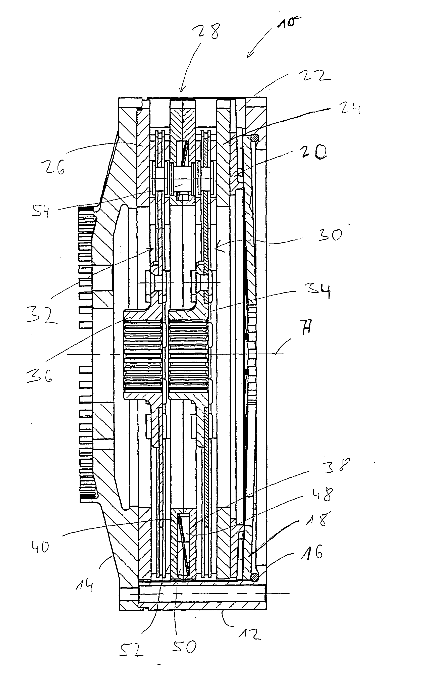
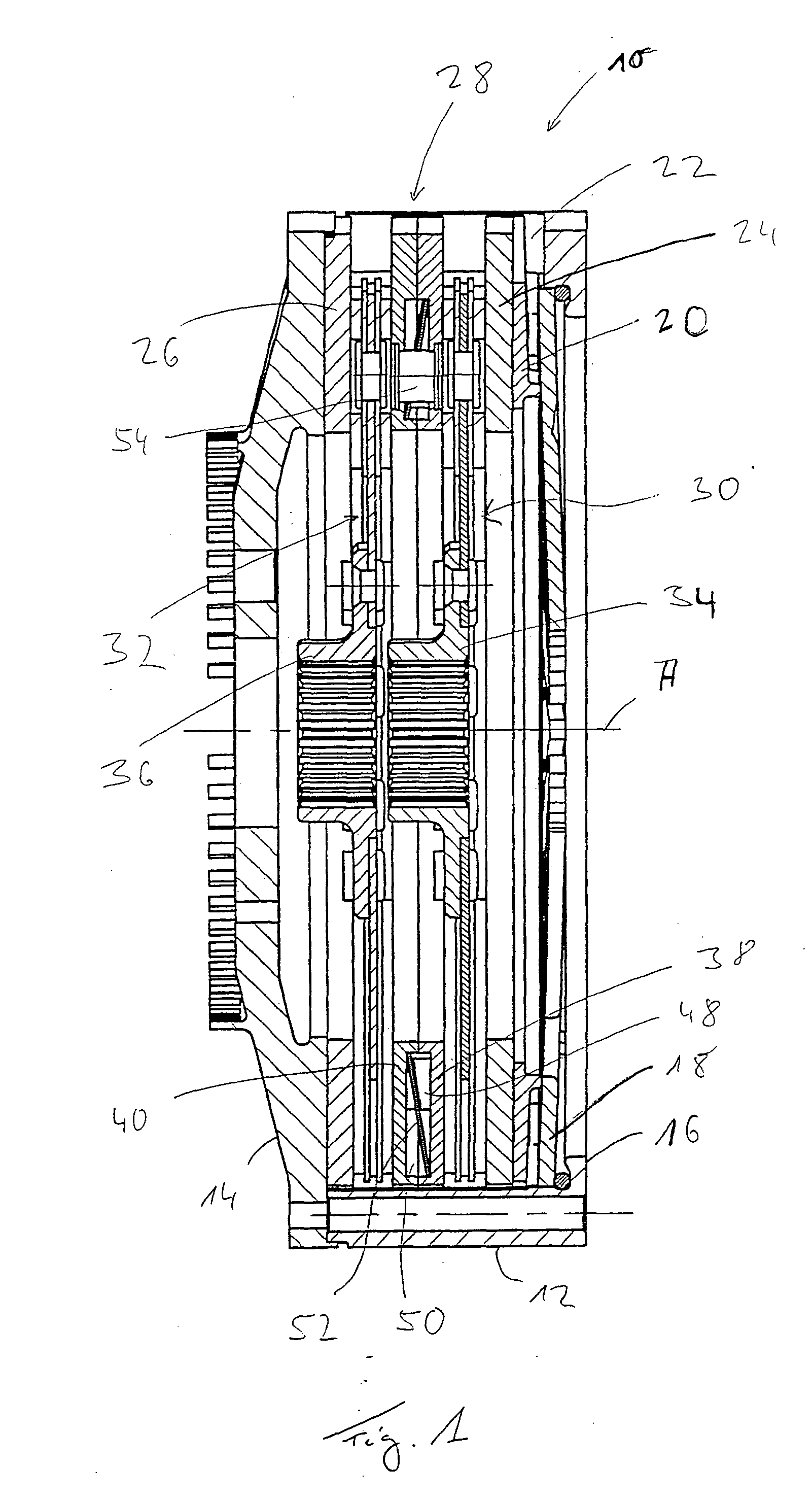
[0019] The clutch arrangement 10 illustrated in FIG. 1 comprises a housing arrangement 12 which is connected fixedly to a flywheel 14 on one axial side by screw bolts or other like fasteners. The other axial side of the housing arrangement 12 forms a supporting region 16 for a force accumulator 18 designed, for example, as a diaphragm spring. The force accumulator 18 acts upon a pressure plate 20 in a region located radially further inward from said supporting region. The pressure plate 20 is coupled fixedly in terms of rotation to the housing arrangement 12, but is displaceable with respect to the latter in the direction of the axis of rotation A. This rotationally fixed coupling may be effected by coupling portions 22 of the housing arrangement 12 which extend in the axial direction and which engage into respective coupling recesses of the pressure plate 20. Axially following the pressure plate 20 and also the flywheel 14, friction plates 24, 26 are provided, so that the pressure ...


PUM


Abstract

A friction clutch includes a housing arrangement having an axis of rotation and an intermediate plate arrangement coupled to the housing arrangement for joint rotation therewith about an axis of rotation. The intermediate plate arrangement is arranged to transmit a pressure force and is preferably arranged between two frictional output members. The intermediate plate arrangement has two intermediate plate elements and an elastic prestressing arrangement therebetween. The two intermediate plate elements being displaceable with respect to one another counter to the action of the elastic prestressing arrangement.

Description

[0001] 1. Field of the Invention[0002] The present invention relates to a friction clutch including a housing arrangement and an intermediate plate arrangement which is arranged between two frictional output members and coupled to a housing arrangement for joint rotation about an axis of rotation.[0003] 2. Description of the Related Art[0004] Friction clutches used in the motor racing sector or in conjunction with high-powered drive assemblies are generally constructed such that they have a plurality of pairings of surfaces coming into frictional interaction with one another. These, on the one hand, are formed on frictional components held fixedly in terms of rotation on the housing side and, on the other hand, are provided on structural parts such as, for example, clutch disks or the like, to be coupled fixedly in terms of rotation to the transmission input shaft or shafts. During the engagement of friction clutches of this type, by the action of a force accumulator upon a pressure...

Claims


Application Information

Patent Timeline
IPC IPC(8): F16D13/38
CPCF16D13/385
Inventor FRIEDRICH, HORSTOBERLE, KLAUS-PETERSELZAM, WERNERISTSCHENKO, MICHAEL
Owner SACHS RACE ENG
Learn More