
State monitoring of a container

a container and state monitoring technology, applied in the field of tracking containers, can solve the problems of central system limited visibility of containers in the global supply chain, failure to provide an evaluation of containers contents, and information failure to account for events occurring between checkpoints

Active Publication Date: 2004-12-09
SAVI TECH INC
View PDF13 Cites 88 Cited by
  • Summary
  • Abstract
  • Description
  • Claims
  • Application Information

AI Technical Summary

Problems solved by technology

However, a central system has limited visibility of containers in the global supply chain.
This high-level information may include verification that the container arrived or departed the checkpoint, and an evaluation of the container based on an external inspection, but fails to provide an evaluation of its contents.
Furthermore, this information fails to account for events occurring between checkpoints that are not detectable at the checkpoint such as extreme humidity or temperatures.
Another drawback of the central system is the delay in alerts concerning the container.
At that time the central system may realize that an alert should be raised, but there is additional delay in brining this to the attention of the operator.
If the scan occurred while loading the container to a ship, the delayed alert may be too late.
Additionally, typical central systems have difficulty in collecting reliable information across heterogeneous systems.
Because the information about what is happening on the container is not first-hand, and is not customized according to characteristics of the container, the central system must make inferences without an ability to verify or reevaluate information.
With increasing traffic in global supply chains, and additional demands of monitoring containers, as well as contents, for economic, security, and logistic purposes, conventional central systems failed to meet these needs.

Method used


Image

  • State monitoring of a container
  • State monitoring of a container
  • State monitoring of a container

Examples


Embodiment Construction

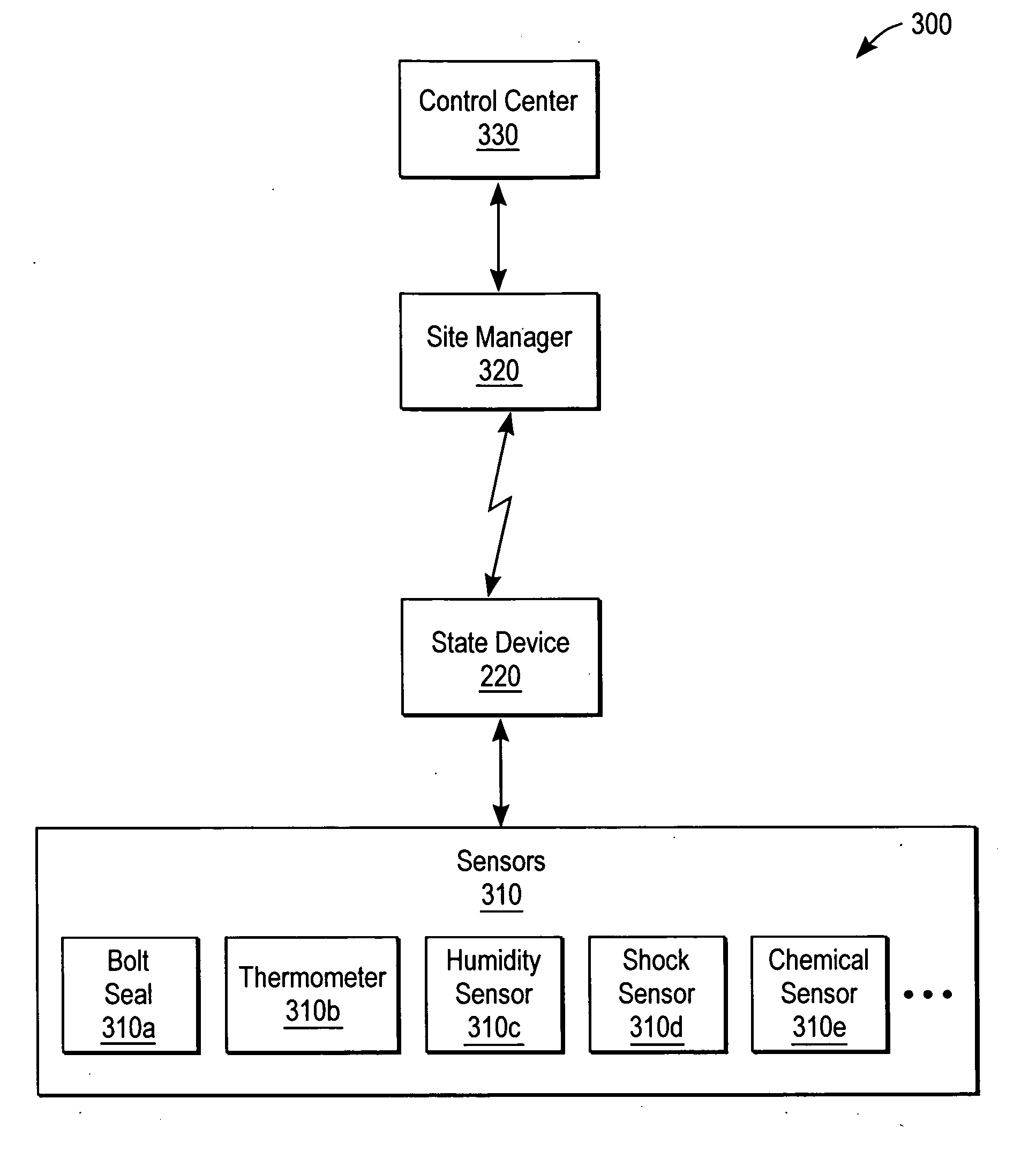
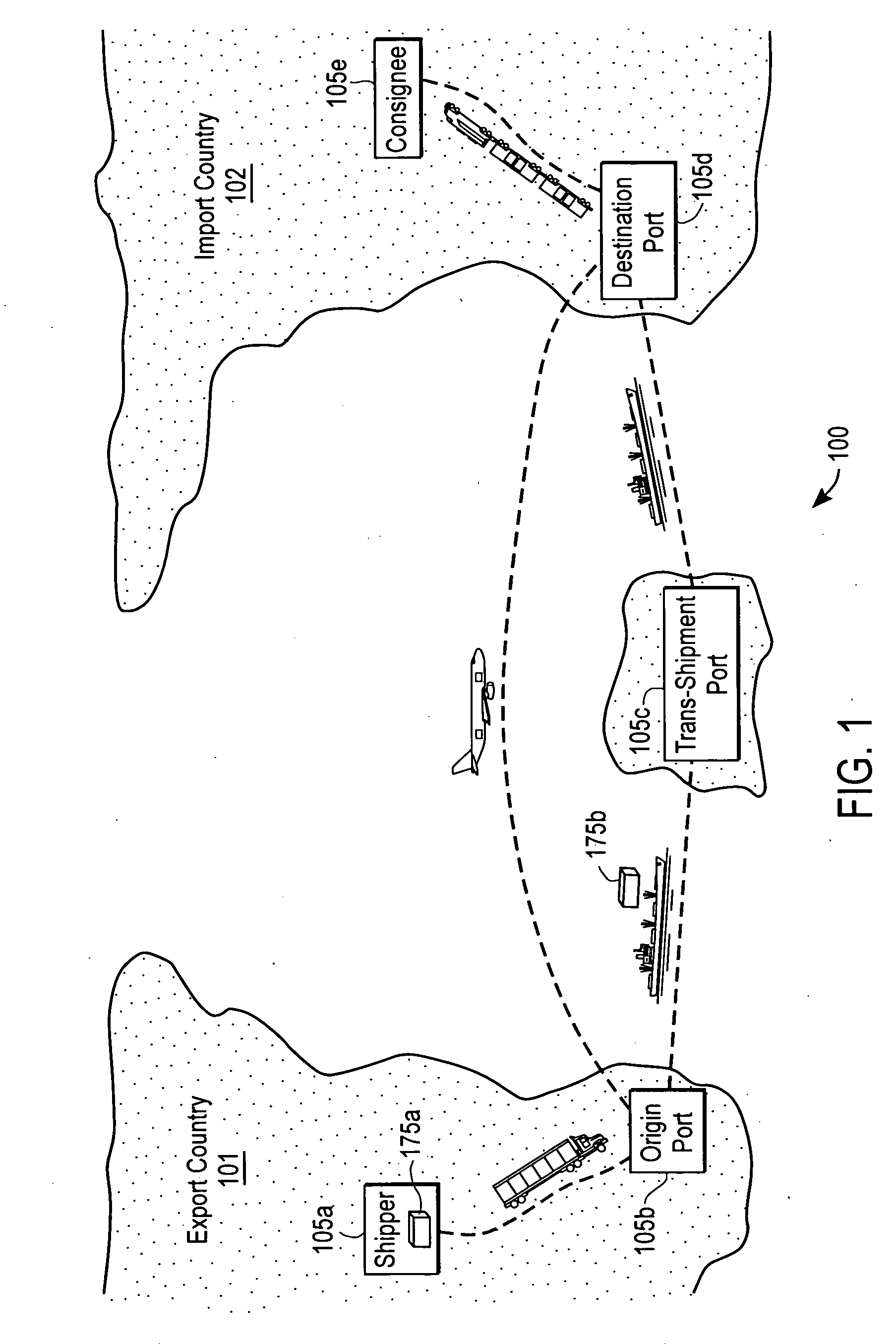
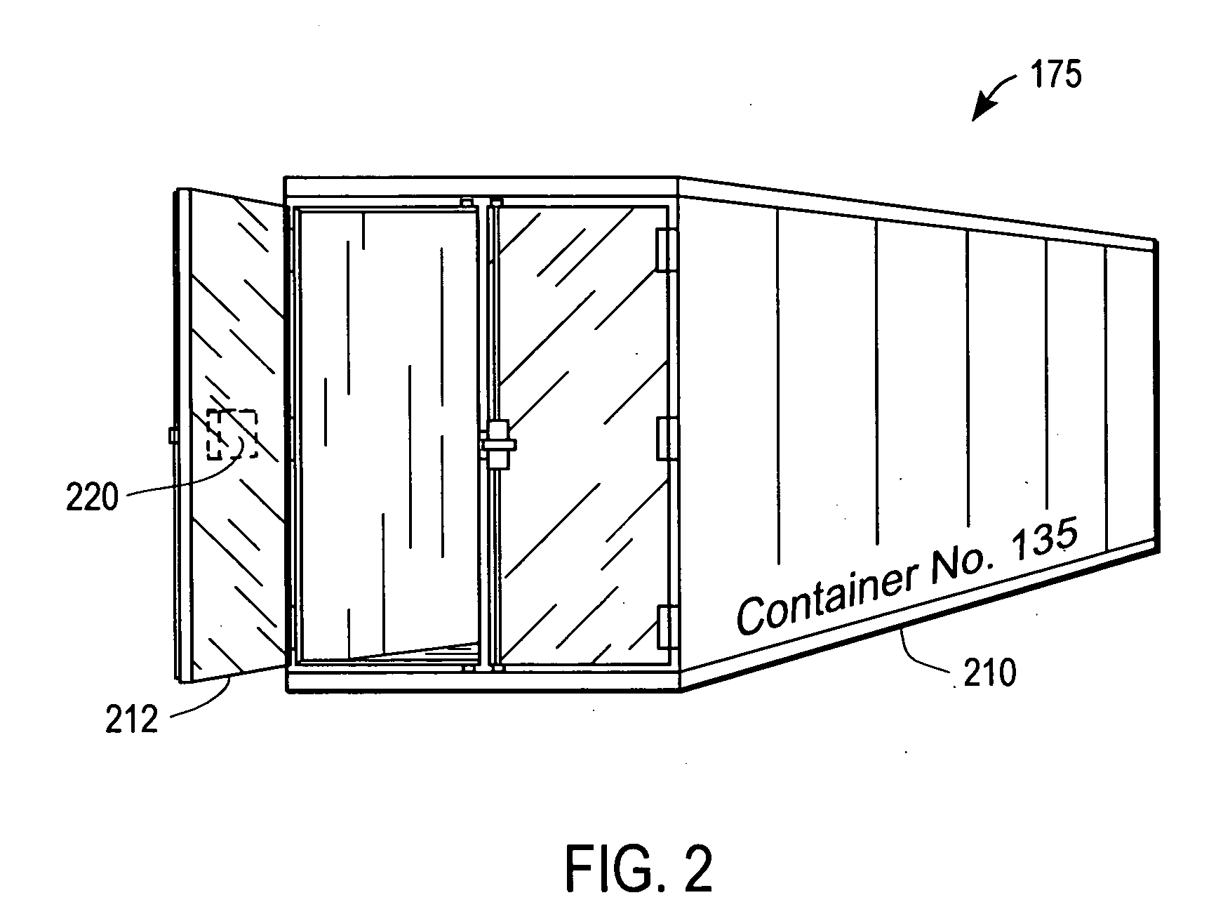
[0023] A system and method for monitoring a state of a container is disclosed. The system according to some embodiments of the present invention is set forth in FIGS. 1-5, and a method operating therein, according to some embodiments of the present invention, is set forth in FIGS. 6-7.

[0024] The accompanying description is for the purpose of providing a thorough explanation with numerous specific details. Of course, the field of container and cargo tracking and monitoring is such that many different variations of the illustrated and described features of the invention are possible. Those skilled in the art will thus undoubtedly appreciate that the invention can be practiced without some specific details described below, and indeed will see that many other variations and embodiments of the invention can be practiced while still satisfying its teachings and spirit. Accordingly, the present invention should not be understood as being limited to the specific implementations described be...


PUM


Abstract

A container for locally determining a container state using a state device. The state device detects unexpected events by comparing expected event information with actual event information related to a container condition. The container condition includes, for example, environmental conditions, logistical or location conditions, and physical or security conditions. Thus, the container is able to intelligently monitor its state and raise an alert without intervention from a central system. The container can also be programmed and reprogrammed with updated logic, states, and / or expected event information. A sensor in the state device gathers input information for comparison to expected event information. A communication port in the state device receives event information. For example, a GPS (Global Positioning System) receiver can determine a current location for comparison to an expected location at the current time. In another example, an RFID (Radio Frequency Identification) receiver and transmitter automatically uploads state information to a central system.

Description

[0001] This application: claims priority under 35 U.S.C. .sctn. 119(e) to U.S. Patent Application No. 60 / 468,930, filed on May 7, 2003, entitled "Concepts for Smart Container," by Stephen Lambright et al.; claims priority under 35 U.S.C. .sctn. 119(e) to U.S. Patent Application No. 60 / 468,929 filed on May 7, 2003, entitled "Concepts for Nested Visibility of Logistics Units," by Stephen Lambright et al.; claims priority under 35 U.S.C. .sctn. 119(e) to U.S. Patent Application No. 60 / 528,334, filed on Dec. 9, 2003, entitled "Concepts for Nested Visibility of Logistics Units," by Stephen Lambright et al.; claims priority under 35 U.S.C. .sctn. 120 as a continuation-in-part to U.S. patent application Ser. No. 10 / 821,296, filed on Apr. 8, 2004, entitled "Continuous Security State Tracking for Intermodal Containers Through a Global Supply Chain," by David Shannon et al., which claims priority under 35 U.S.C. .sctn. 119(e) to U.S. Provisional Patent Application No. 60 / 461,946, filed on Apr...

Claims


Application Information

Patent Timeline
IPC IPC(8): G06Q10/00G08B13/24G08B25/10
CPCG06Q10/08G08B13/2462G08B25/10G06Q10/0832
Inventor LAMBRIGHT, STEPHEN J.LACORTE, BLAIR B.SHANNON, DAVID L.RAJAPAKSE, RAVINDRA U.FARRELL, STEVEN J.
Owner SAVI TECH INC
Learn More