Image forming apparatus
- Summary
- Abstract
- Description
- Claims
- Application Information
AI Technical Summary
Benefits of technology
Problems solved by technology
Method used
Image

Examples
first embodiment
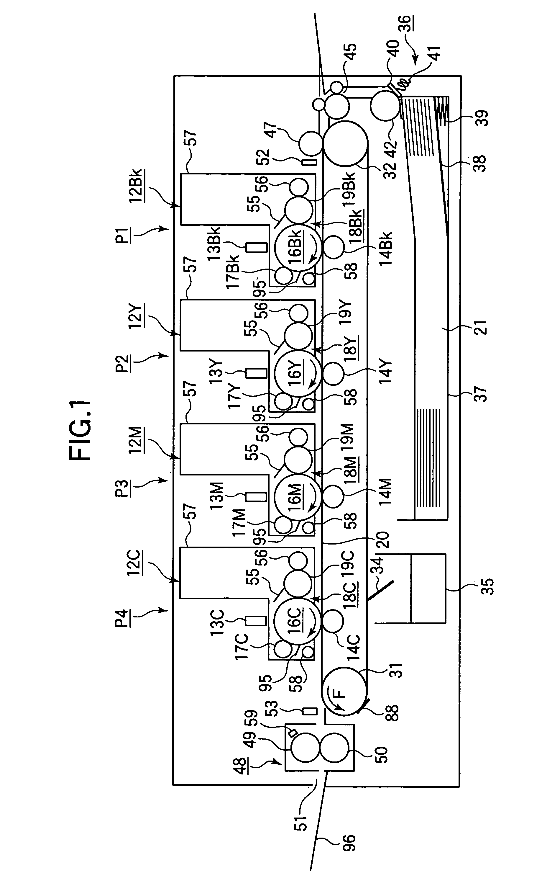
[0054] FIG. 1 illustrates a general configuration of a printer according to a
[0055] Referring to FIG. 1, a tandem type printer includes first to fourth print engines P1-P4 aligned in a direction in which a recording medium 21 such as paper and OHP is transported for printing. The print engines P1-P4 are an electrophotographic LED printing mechanism.
[0056] The first print engine P1 prints black images and includes an image forming section 12BK, an LED head 13BK, and a transfer roller 14BK. The LED head 13BK illuminates the charged surface of a photoconductive drum 16BK in accordance with print data. The transfer roller 14BK transfers a toner image formed on the photoconductive drum 16BK onto the recording medium 21.
[0057] The second print engine P2 prints yellow images and includes an image forming section 12Y, an LED head 13Y, and a transfer roller 14Y. The LED head 13Y illuminates the charged surface of a photoconductive drum 16Y in accordance with print data. The transfer roller 1...
second embodiment
[0150] A second embodiment differs from the first embodiment in that the image forming sections 12BK, 12Y, 12M, and 12C are movable upward to the non-operation position (FIG. 11) and downward to the operative position (FIG. 12). Elements similar to those in the first embodiment have been given the same references and the description is omitted.
[0151] FIG. 11 is a side view in schematic form illustrating a printer according to the second embodiment when the image forming sections are at the non-operative position.
[0152] The image forming sections 12BK, 12Y, 12M, and 12C are movable downward to the operative position and upward to the non-operative position. The controller 61 performs a cooling operation in which a check is made to determine whether the detected temperature Tb is higher than the threshold .phi. (e.g., 50.degree. C. in the second embodiment) If Tb>.phi., an up-down mechanism controller 101 (FIG. 15B) controls a drive motor 138 (FIG. 15B) to drive the up-down mechanism ...
third embodiment
[0189] Elements similar to those in the first embodiment have been given like reference numerals and the description thereof is omitted.
[0190] FIG. 16 is a side view in schematic form illustrating a printer according to a third embodiment when the image forming sections are at the non-operative position.
[0191] FIG. 17 is an enlarged view illustrating a pertinent portion of a path-switching unit.
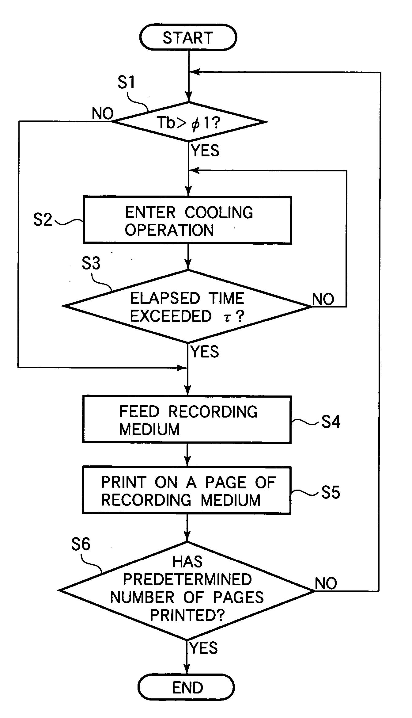
[0192] FIG. 18 is a flowchart illustrating the operation of the printer.
[0193] The printer incorporates a medium turning unit 180 detachably mounted. In the normal printing operation, after printing is performed on one side of a recording medium 21 the recording medium is fed into the medium-turning unit 180 where the recording medium 21 is turned over so that its underside becomes its top side. Thus, the recording medium is ready for subsequent printing on the other side of the recording medium 21. In the third embodiment, the medium-turning unit 180 is utilized to pass the recording medium ...
PUM
 Abstract
Description
Claims
Application Information
 - R&D Engineer
- R&D Manager
- IP Professional
- Industry Leading Data Capabilities
- Powerful AI technology
- Patent DNA Extraction
Browse by: Latest US Patents, China's latest patents, Technical Efficacy Thesaurus, Application Domain, Technology Topic.
© 2024 PatSnap. All rights reserved.Legal|Privacy policy|Modern Slavery Act Transparency Statement|Sitemap