Device for de-rinding and skinning a product to be treated

a technology for skinning and product, which is applied in the field of devices for skinning and derind can solve the problems of time-consuming and expensive procedures, no other products to be treated, and only one side skinning of products to be treated

Inactive Publication Date: 2004-12-09
MAJA-MASCHINENFABRIK HERMAN SCHILL KG
View PDF8 Cites 13 Cited by
  • Summary
  • Abstract
  • Description
  • Claims
  • Application Information

AI Technical Summary

Problems solved by technology

The known devices have the disadvantage that the product to be treated is only skinned from one side.
This type of procedure is time-consuming and expensive.
Thus, no other product to be treated can be fed to the first skinning unit until the product to be treated has left the first skinning unit.

Method used


Image

  • Device for de-rinding and skinning a product to be treated
  • Device for de-rinding and skinning a product to be treated
  • Device for de-rinding and skinning a product to be treated

Examples


Embodiment Construction

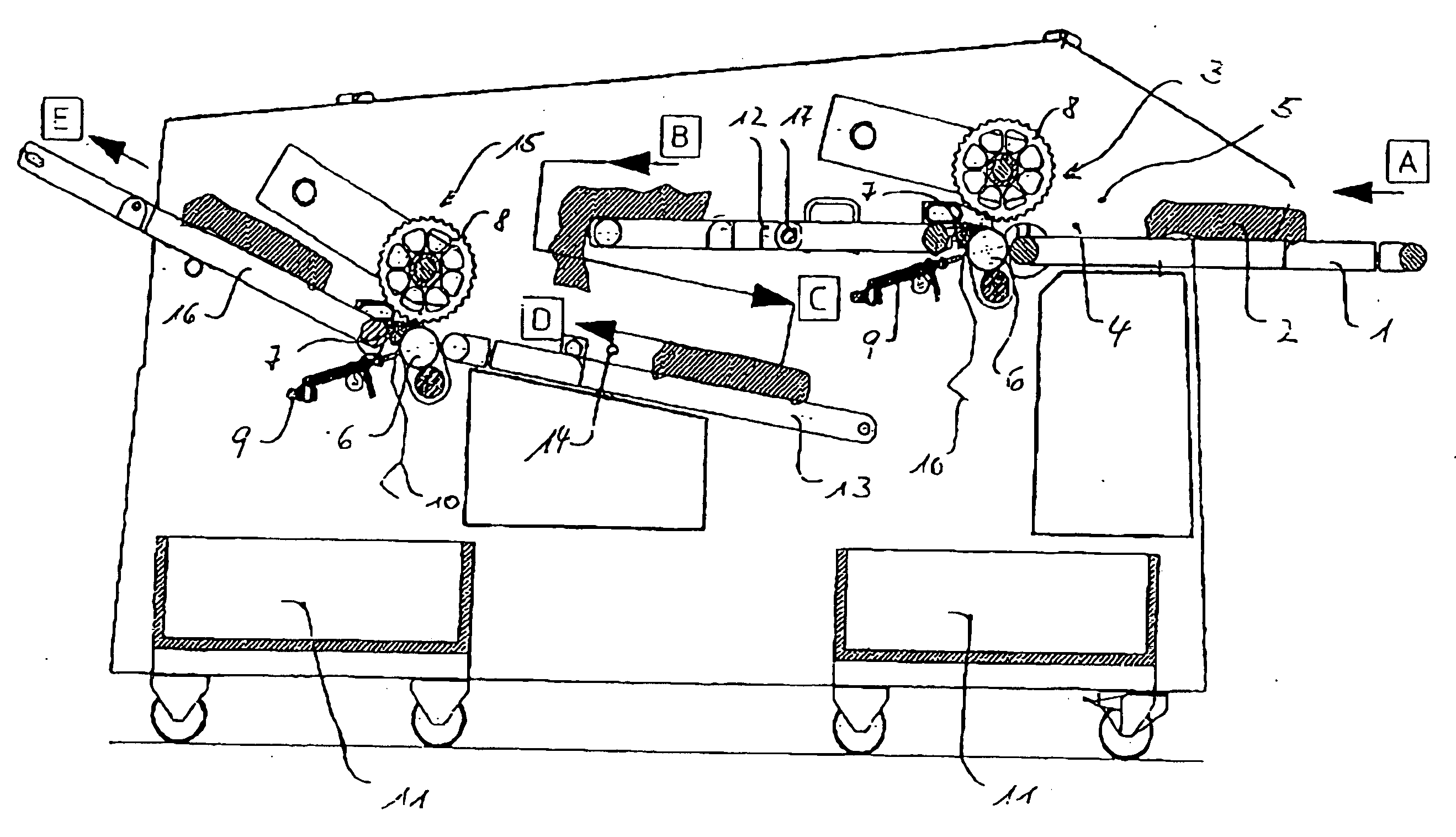
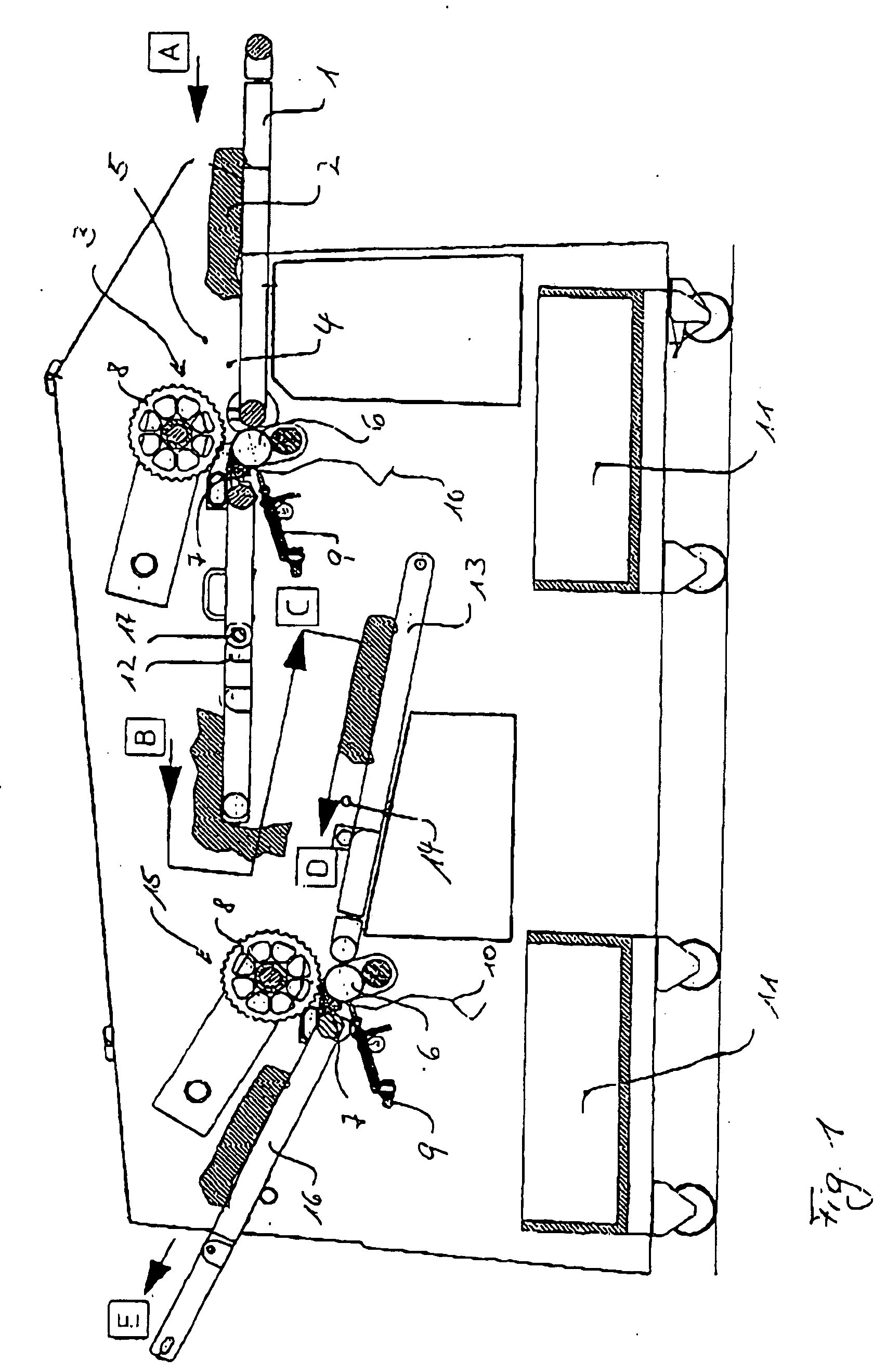
[0022] FIG. 1 shows the side view of a device for de-rinding and skinning. A piece of meat 2 is fed to a first skinning unit 3 via a supply belt 1. The length and the thickness of the piece of meat are recognized by the two photo sensors 4 and 5. When the piece of meat has completely passed the photo sensor 4, the supply belt 1 stops. Thus, no further piece of meat can be fed to the first skinning unit 3. The piece of meat 2 is now taken hold of by the rotating drawing roller 6 and is fed to the skinning blade of the cutting unit 7. A press roller 8 ensures that the piece of meat is pressed from above against the cutting unit 7. Pieces of meat that stick to the drawing roller 6 are removed by a compressed-air device 9. The fat and skin remains 10 removed by the cutting unit fall downward into an accumulation bin11. The piece of meat 2 skinned on the bottom is transported away from the first skinning unit 3 by the first removal belt 12. The transport direction of the supply belt 1 an...


PUM


Abstract

The invention relates to a device for skinning and de-rinding a product to be treated such as pieces of meat or fish and similar products (2), said product to be treated being first skinned from one side by means of a first skinning unit (3). A combination of a first conveyer belt (12) and a reversing belt (13) reverses the piece of meat. A second skinning unit (15 removes the remaining fat and skin (10) from the other side of the product (2) to be treated.

Description

STATE OF THE ART[0001] The invention concerns a device for the de-rinding and skinning of a product to be treated in accordance with the preamble of claim 1.[0002] Such devices serve to remove from a product to be treated undesirable layers like fat or skin, in particular, from pieces of meat or fish. The product to be treated is taken hold of by means of a drawing roller and is pressed against the cutting element of a cutting unit. The cutting element is, for example, a blade. By rotating the drawing roller, the product to be treated is moved relative to the cutting element and the undesired layer of the product to be treated is removed by the cutting element. An additional press roller serves to press the product to be treated against the cutting unit. The predominantly flat product to be treated is continuously moved over and away from the cutting unit by the drawing roller and the press roller without being turned. Such devices are, for example, known from EP 197 39 618 A1 and D...

Claims


Application Information

Patent Timeline
Patent Type & Authority Applications(United States)
IPC IPC(8): A22B5/16A22C25/17
CPCA22B5/166A22C25/17
Inventor SCHILL, JOACHIM
Owner MAJA-MASCHINENFABRIK HERMAN SCHILL KG
Why Eureka
Try Eureka